LiftMaster JDC Installation Manual - English French Spanish - Page 45
Troubleshooting
 |
View all LiftMaster JDC manuals
Add to My Manuals
Save this manual to your list of manuals |
Page 45 highlights
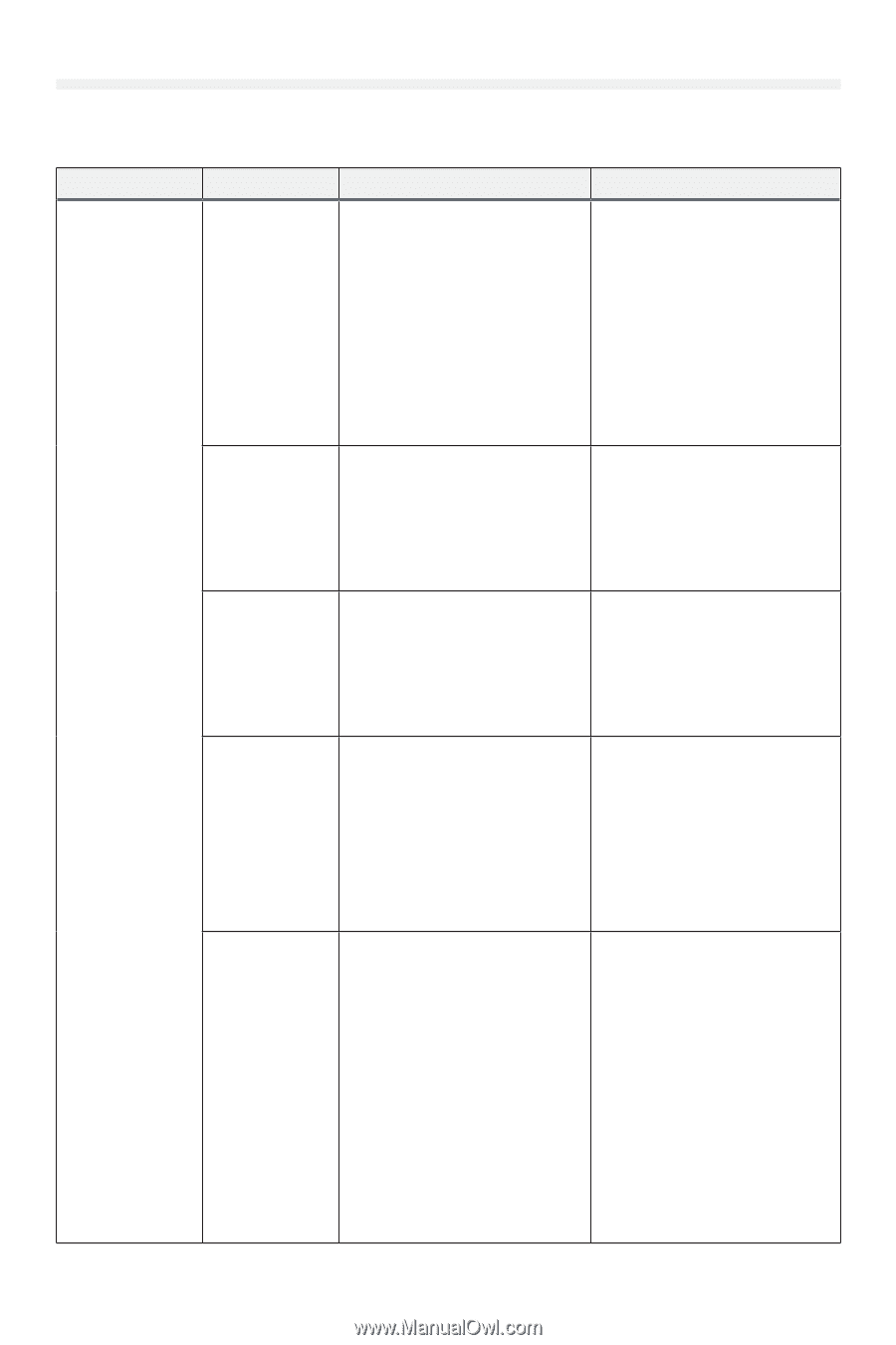
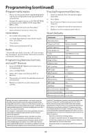
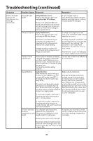
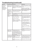
Troubleshooting Additional Troubleshooting The table below is a guide for best practice system troubleshooting, containing potential causes and corrective actions. Symptom Powerhead main board is off (no LEDs are lit or blinking) (continued) Possible Causes Diagnosis Resolution Transformer is overheating Transformer has an internal thermal protection device which disconnects AC power if the transformer overheats. If the transformer is allowed to cool, AC power should reconnect and restore power to the operator. Transformer should not normally overheat. If overheating occurs: Check door for imbalance and/or resistance Check ambient temperature and ensure it is within the operational ratings of the door operator. AC power absent or out of range AC input voltage mis-selected (120V/240V models only) Ensure that air can move freely around the door operator, and that dust or other foreign matter is not preventing airflow. Verify input AC voltage: Measure AC voltage between 'L1' and 'L2' terminals at EMI filter board input connector. Verify voltage is within specifications. If voltage is outside specifications, see resolution. If voltage is absent, restore power to the operator. Check for tripped breakers, blown fuses, faulty AC wiring, open disconnects, etc. If voltage is out of specification, consult an electrician. Check whether the transformer connector is plugged in to the connectors on the EMI filter board marked '120V' or '240V.' If 240V power is applied when 120V is selected, damage to other components of the operator electronics may have occurred. Blown DC input fuses on main board Verify this matches the input AC voltage supplied to the operator. Ensure voltage selection is corrected and verify the operator functions. Check fuses: Replace both DC IN fuses with Measure voltage across DC IN fuses. automotive style ATO or ATC fuses, 30A 32V. Both DC IN fuses must If voltage is greater than 0.5V, fuses be present and intact for proper are blown. See resolution. operation of the door operator. Fuses may also be visually inspected. Fuses should have their internal metallic fuse element intact. If there is a break in the fuse element, fuse is blown. Faulty Powerhead main board Perform this test only after first checking fuses. Measure DC voltage between 'DC IN' + and - terminals. Voltage should be between 30 and 48 volts DC with motor stopped. If voltage is present and MAIN PWR LED is not lit, see resolution. Turn off AC power and disconnect batteries (if present) for at least 30 seconds, then reconnect batteries (if present) and turn on AC power. If no LEDs are lit after cycling power, cycle power again as above but disconnect all cabling from mainboard except for main power wiring before restoring batteries/ AC power. If LEDs still do not light, replace main board. If LEDs light after disconnecting other devices, suspect a short or overload from a connected device. 45
-
 1
1 -
2
-
3
-
4
-
5
-
6
-
7
-
8
-
9
-
10
-
11
-
12
-
13
-
14
-
15
-
16
-
17
-
18
-
19
-
20
-
21
-
22
-
23
-
24
-
25
-
26
-
27
-
28
-
29
-
30
-
31
-
32
-
33
-
34
-
35
-
36
-
37
-
38
-
39
-
 40
40 -
 41
41 -
 42
42 -
 43
43 -
 44
44 -
 45
45 -
 46
46 -
 47
47 -
 48
48 -
 49
49 -
 50
50 -
51
-
52
-
53
-
54
-
55
-
56
-
57
-
58
-
59
-
60
-
61
-
62
-
63
-
64
-
65
-
66
-
67
-
68
-
69
-
70
-
71
-
72
-
73
-
74
-
75
-
76
-
77
-
78
-
79
-
80
-
81
-
82
-
83
-
84
-
85
-
86
-
87
-
88
-
89
-
90
-
91
-
92
-
93
-
94
-
95
-
96
-
97
-
98
-
99
-
100
-
101
-
102
-
103
-
104
-
105
-
106
-
107
-
108
-
109
-
110
-
111
-
112
-
113
-
114
-
115
-
116
-
117
-
118
-
119
-
120
-
121
-
122
-
123
-
124
-
125
-
126
-
127
-
128
-
129
-
130
-
131
-
132
-
133
-
134
-
135
-
136
-
137
-
138
-
139
-
140
-
141
-
142
-
143
-
144
-
145
-
146
-
147
-
148
-
149
-
150
-
151
-
152
-
153
-
154
-
155
-
156
-
157
-
158
-
159
-
160
-
161
-
162
-
163
-
164
-
165
-
166
-
167
-
168
-
169
-
170
-
171
-
172
-
173
-
174
-
175
-
176
-
177
-
178
-
179
-
180
-
181
-
182
-
183
-
184
-
185
-
186
-
187
-
188
-
189
-
190
-
191
-
192
-
193
-
194
-
195
-
196
-
197
-
198
-
199
-
200
-
201
-
202
-
203
-
204
-
205
-
206
-
207
-
208
-
209
-
210
-
211
-
212
-
213
-
214
-
215
-
216
 |
 |