LiftMaster SW420 SW420 GL BOARD Manual - Page 12
Control Arm Assembly - manual
 |
View all LiftMaster SW420 manuals
Add to My Manuals
Save this manual to your list of manuals |
Page 12 highlights
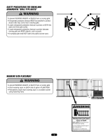
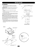
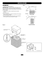
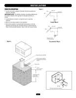
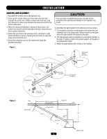
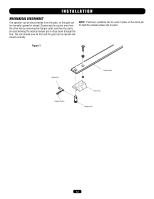
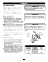
INSTALLATION WARNING CONTROL ARM ASSEMBLY 1. Assemble the control arm to the operator hub. 2. Push up the manual release pin from below the hub and through the control arm. Retain in place with clevis pin. Use 3/8" washers to reduce play between the clevis pin and the top of the control arm. 3. When the manual release pin is allowed to drop down, the control arm should swivel freely about the hub. Leave the arm free to pivot at this time. 4. Fasten the arm stop to the extension arm. Left hand or right hand installations call for mounting the arm stop on opposite sides of the extension arm. 5. Secure the extension arm to the control arm using the hardware provided. Figure 1 Arm Kit 307072703R CAUTION If the arm stop is installed incorrectly, the gate will be prevented from opening and damage to the operator may result! 6. Assemble the gate bracket to the extension arm as shown. 7. Put the gate in the fully closed position and extend the arm AVERT assembly out to the closed gate. Mark the point on the gate where the gate bracket will mount to the gate. 8. The gate bracket must be installed on a structural member of the gate. If require, install a horizontal support on the gate at the appropriate height. 9. Attach the gate bracket with U-bolts or by welding. AVERT Extension Arm Gate Bracket Bolt Kit K75-19314 Gate Bracket ATTEN AVER Arm Stop (Right Open) Figure 2 Control Arm (As Required) Drive Hub Disconnect Kit K75-18625 Drive Hub on Operator Arm Stop (Left Open) Arm Stop Kit K75-18624 ADVERTENCIA PRECAUCIÓN Gate 36-1/2" Hinge Pin (Approximately) Fence Gate Bracket Extension Arm 16" 33-1/2" 28" Control Arm Arm Stop 26" Operator Shaft 12
-
 1
1 -
2
-
3
-
4
-
5
-
6
-
 7
7 -
 8
8 -
 9
9 -
 10
10 -
 11
11 -
 12
12 -
 13
13 -
 14
14 -
 15
15 -
 16
16 -
 17
17 -
18
-
19
-
20
-
21
-
22
-
23
-
24
-
25
-
26
-
27
-
28
-
29
-
30
-
31
-
32
-
33
-
34
-
35
-
36
 |
 |