LiftMaster SW420 SW420 GL BOARD Manual - Page 18
RPM Sensor (Hall Effect) Adjustment, Normally the RPM sensor hall effect does not need, adjustment
 |
View all LiftMaster SW420 manuals
Add to My Manuals
Save this manual to your list of manuals |
Page 18 highlights
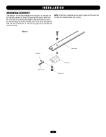
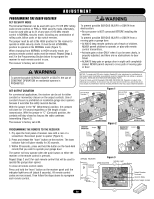
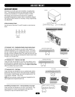
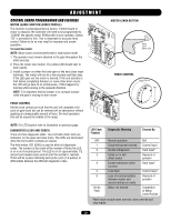
ADJUSTMENT RPM SENSOR (HALL EFFECT) ADJUSTMENT NOTE: Normally the RPM sensor (hall effect) does not need adjustment, but may go out of alignment due to shipping vibration or rough handling. These operators use an internal entrapment protector system. This system consists of the control board, magnet, and RPM sensor. It may become necessary to adjust the sensor for correct alignment. To do so please perform the following steps: 1. Loosen the two screws holding the hall bracket to the frame. 2. Adjust the bracket so that the sensor is: a. Parallel with the pulley. b. .020" (.051 cm) away from the pulley's magnet. Use a feeler gauge to measure the distance. 3. Tighten screws to secure assembly. 4. Manually rotate pulley to ensure that each magnet clears the sensor board. If a magnet does not clear the board, re-adjust the RPM (hall effect) assembly accordingly. WARNING To reduce the risk of SEVERE INJURY or DEATH: CAUTION • Disconnect power BEFORE performing ANY adjustments. AVERT AVERT ATTEN Cable Operator Chassis Mounting Screws (2) Bracket Pulley Magnet AVER Pulley ADVERTENCIA PRECAUCIÓN 18
-
 1
1 -
2
-
3
-
4
-
5
-
6
-
7
-
8
-
9
-
10
-
11
-
12
-
 13
13 -
 14
14 -
 15
15 -
 16
16 -
 17
17 -
 18
18 -
 19
19 -
 20
20 -
 21
21 -
 22
22 -
 23
23 -
24
-
25
-
26
-
27
-
28
-
29
-
30
-
31
-
32
-
33
-
34
-
35
-
36
 |
 |
