LiftMaster SW420 SW420 GL BOARD Manual - Page 9
Installation, Post Mounting
 |
View all LiftMaster SW420 manuals
Add to My Manuals
Save this manual to your list of manuals |
Page 9 highlights
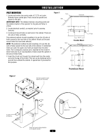
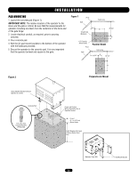
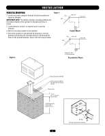
INSTALLATION POST MOUNTING 1. Locate and anchor two posts made of 3" (7.6 cm) outer diameter heavy walled pipe. Posts should be parallel and square to the gate. IMPORTANT NOTE: The distance between mounting posts and the relative location of the operator to the gate and fence is critical. 2. Locate electrical conduit, as required, prior to pouring concrete. 3. Locate post mount holes on each end of the cabinet. There are (3) sets of holes vertically. The preferred method of post mounting is to use the (2) sets of holes nearest to the rear side of the cabinet. Knock out the post mount holes that have been selected. NOTE: The preferred method of post mounting is to use the (2) sets of holes nearest to the rear side of the cabinet. If mentioned holes are used, the upper rear holes are larger than the other holes. This is because a special nut is required for the U-bolt in these holes due to an inaccessibility of tools inside the cabinet in the area of these holes. 4. Insert the U-bolt nut through the cabinet wall from the inside and onto the leg of the U-bolt. This nut can be tightened with a wrench from outside the cabinet. A special tool is provided for this purpose. Figure 1 Pivot Gate Fence Line 5-3/8" 3" 11" 21-1/4" Pivot Gate 18-1/4" Parallel Mount Fence Line 17-3/8" 16" 18-1/4" 21-1/4" 28" 3" Pipe Perpendicular Mount Figure 2 Use tool provided to insert special nut in rear holes. 3" U-bolt (4 required) Rear of cabinet Special nut Power and control wiring should be run in separate conduit 9
-
 1
1 -
2
-
3
-
 4
4 -
 5
5 -
 6
6 -
 7
7 -
 8
8 -
 9
9 -
 10
10 -
 11
11 -
 12
12 -
 13
13 -
 14
14 -
15
-
16
-
17
-
18
-
19
-
20
-
21
-
22
-
23
-
24
-
25
-
26
-
27
-
28
-
29
-
30
-
31
-
32
-
33
-
34
-
35
-
36
 |
 |
