LiftMaster SW420 SW420 GL BOARD Manual - Page 15
On/Off Switch Power Wiring, Stop/Reset Button Control Wiring (Required), The operator will
 |
View all LiftMaster SW420 manuals
Add to My Manuals
Save this manual to your list of manuals |
Page 15 highlights
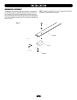
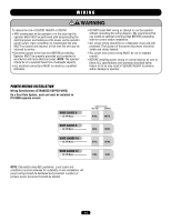
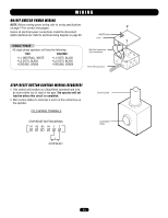
WIRING ON/OFF SWITCH POWER WIRING NOTE: Before running power wiring refer to wiring specifications on page 14 for correct wire gauges. Secure all electrical power connections inside the disconnect switch electrical box. Refer to electrical wiring diagram on page 30. ON/OFF Switch Cover SINGLE PHASE All single phase operators will have the following: 115V 208/230V • L1 (NEUTRAL), WHITE • L2 (HOT), BLACK • GROUND, GREEN • L1 (HOT), BLACK • L2 (HOT), BLACK • GROUND, GREEN Wire Nut Connections (See Instructions) Power Wiring Conduit STOP/RESET BUTTON CONTROL WIRING (REQUIRED) 1. This control will function as a Stop/Reset command and is to be wired within line of sight of the gate. The operator will not function unless this circuit is completed. 2. Wire control station to terminals 3 and 5 in the control box on the operator. FIELD WIRING TERMINALS STOP/RESET BUTTON WIRING R1 R2 R3 R4 3 5 Control Conduit STOP/RESET Button STOP/RESET 15
-
 1
1 -
2
-
3
-
4
-
5
-
6
-
7
-
8
-
9
-
 10
10 -
 11
11 -
 12
12 -
 13
13 -
 14
14 -
 15
15 -
 16
16 -
 17
17 -
 18
18 -
 19
19 -
 20
20 -
21
-
22
-
23
-
24
-
25
-
26
-
27
-
28
-
29
-
30
-
31
-
32
-
33
-
34
-
35
-
36
 |
 |
