LiftMaster SW420 SW420 GL BOARD Manual - Page 28
TROUBLESHOOTING continued, Master or Second
 |
View all LiftMaster SW420 manuals
Add to My Manuals
Save this manual to your list of manuals |
Page 28 highlights
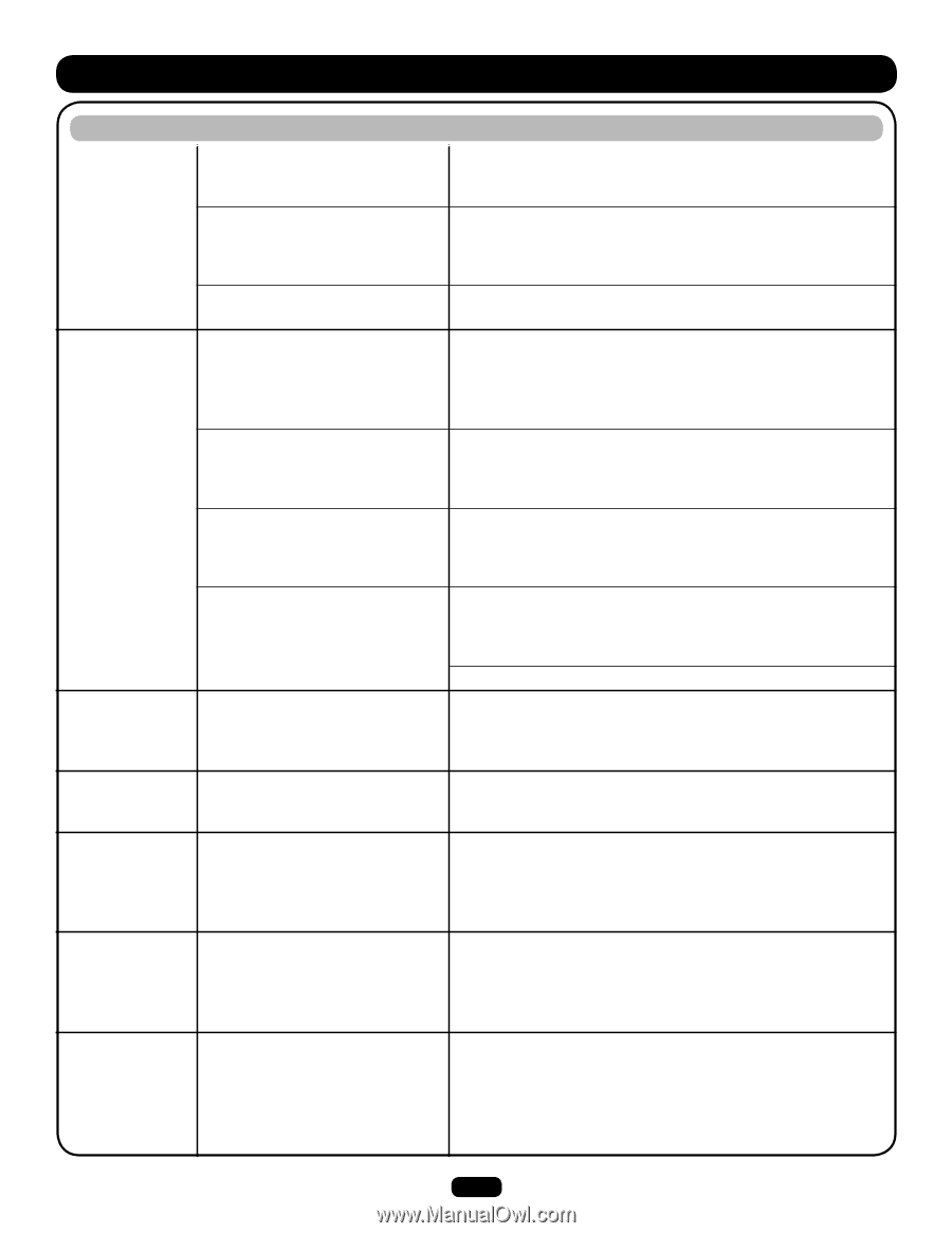
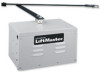
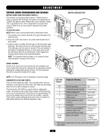
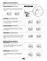
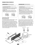
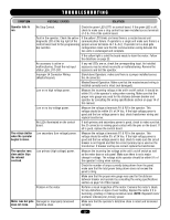
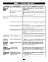
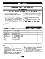
TROUBLESHOOTING continued SYMPTOM Master or Second operator is not functioning properly. Operator runs but then stops and reverses direction. POSSIBLE CAUSES SOLUTION Failure to cycle power after setup. The power to each unit must be cycled in order to initiate proper master/second communication if the operators were previously in stand-alone mode. The communication wiring may be damaged or improperly wired for dual gate operation. Make sure that the communication wire that is used is twisted pair and not run in the same conduit with any power wiring. Failure to do so will result in interference across the master/second communication line. The master or second unit is not programmed correctly. Review program settings pages 25-26 and check both the master and second for proper programming. Entrapment (Force Pot) incorrectly set. This pot must be set so that the gate will run smoothly normally and reverse when encountering an obstruction. See page 23. Gate is binding or not running smoothly. Disconnect the gate from the operator and swing the gate open and close by hand at normal operating speed. Make sure that the gate swings smoothly and does not bind. If the gate is hard to move or binds repair the gate. Observe red LEDs D29 and D31. Both LEDs will indicate the activation of entrapment protection devices on terminals J1-9 & J1-10 on the control board. Remove the devices and retest. If the operator now runs without fault, check those accessories as well as their wiring. The Hall Effect Sensor is not aligned/ adjusted correctly. Make sure that the sensor is adjusted so that it is within 20 thousandths of an inch or as close to the magnets located on the gearbox pulley as possible without coming into contact with them or the pulley. The operator opens immediately upon power up and does not close. Check the red input status LEDs, D11-D31, for indication of an active or malfunctioning accessory. Replace the sensor if it is adjusted correctly but continues to fail. If any red LEDs are on, check the corresponding input. An installed accessory may be wired incorrectly or malfunctioning. Remove the accessory and test the operator. Programming changes do not effect the gate. Check the save switch on switch S1-1. If the switch S1-1 is in the on position any subsequent programming changes will not affect the gate. To make programming changes, switch S1-1 off, make desired changes, and then switch S1-1 on. Open photo eye reverses gate closed when activated during opening. Open obstruction input is programmed The open obstruction input has been programmed to function with incorrectly. gate edges not photo eyes. Refer to page 26 and reprogram the obstruction inputs for correct operation. Gate does not Close obstruction input is activate the timer to programmed incorrectly. close after the close photo eye is broken. The close obstruction input has been programmed to function with gate edges not photo eyes. Refer to page 26 and reprogram the obstruction inputs to match the accessories that are installed on the operator. Radio controls will Radio terminals R1-4 are factory close gate from the configured for residential (Open and open limit. Close) radio function. Configure terminals R1-4 for residential radio function by performing the following modifications: 1. Locate and disconnect the end of the wire running to terminal J1-1 from R4. 2. Connect the end of wire removed from J1-1 to J1-6. Refer to page 34. 28
-
 1
1 -
2
-
3
-
4
-
5
-
6
-
7
-
8
-
9
-
10
-
11
-
12
-
13
-
14
-
15
-
16
-
17
-
18
-
19
-
20
-
21
-
22
-
 23
23 -
 24
24 -
 25
25 -
 26
26 -
 27
27 -
 28
28 -
 29
29 -
 30
30 -
 31
31 -
 32
32 -
 33
33 -
34
-
35
-
36
 |
 |