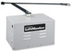
LiftMaster SW420 SW420 GL BOARD Manual - Page 2
Table of Contents - gate operator
 |
View all LiftMaster SW420 manuals
Add to My Manuals
Save this manual to your list of manuals |
Page 2 highlights
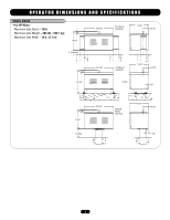
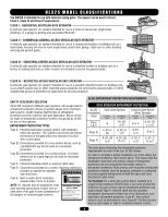
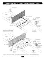
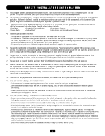
TABLE OF CONTENTS OPERATOR SPECIFICATIONS Carton Inventory 2 Operator Dimensions and Specifications 3 UL325 Model Classifications 4 OPERATOR WARNINGS Suggested Safety Protection Device Locations 5 Safety Installation Information 6 Gate Construction Information 7 Safety Precautions for Swing and Ornamental "Grill Type Gates 8 Warning Sign Placement 8 INSTALLATION Post Mounting 9 Pad Mounting 10 Pedestal Mounting 11 Control Arm Assembly 12 Mechanical Disconnect 13 WIRING Power Wiring Installation 14 On/Off Switch Power Wiring 15 Stop/Reset Button Control Wiring (Required 15 ADJUSTMENT Programming the Radio Receiver 16 Limit Switch Adjustment 17 RPM Sensor (Hall Effect) Adjustment 18 Sequenced Access Management System (SAMS 19 Accessory Wiring 20-21 Control Board Illustration 22 Controller Programming and Features 23-24 Program Settings 25-26 TROUBLESHOOTING 27-28 MAINTENANCE Operator Maintenance 29 Single Phase Wiring Diagram 30 Repair Parts 31 Illustrated Parts 32 Safety Accessories for Secondary Entrapment Protection . . . . .33 Control Connection Diagrams 34 OPERATOR NOTES 35 WARRANTY POLICY 36 IMPORTANT NOTE • BEFORE attempting to install, operate or maintain the operator, you MUST read and fully understand this manual and follow all safety instructions. • These instructions are intended to highlight certain safety related issues. These instructions are not intended to be comprehensive. Because each application is unique, it is the responsibility of the purchaser, designer, installer and end user to ensure that the total gate system is safe for its intended use. CARTON INVENTORY Before beginning your installation check that all components were supplied and received undamaged. Refer to list below for factory supplied parts. HARDWARE KIT SW420 (K77-SW420) PART NO. 01-G0582 02-401-SP 07-2705 10-2111 11-2754 12-2727 40-3505 80-10026 80-206-65 80-2754 82-HN38-16 82-HN38-18 82-SH37-10 85-FW-38S DESCRIPTION Safety Gate Brochure Stop Button Arm Stop Gate Bracket U-Bolt Nut Tool Bushing 3/8" Warning Sign Washer, Shim 3/8" Spacer U-Bolt Nut Bolt 3/8-16 x 1" Hex Head Bolt 3/8-16 Socket Head Bolt 3/8-24 Flat Washer 3/8" QTY. 1 1 1 1 1 3 2 2 4 2 1 2 1 1 WARNING Mechanical CWAUATRIONINNG Electrical CAWUATRIONNING WARNING When you see these Safety Symbols and Signal Words on the following pages, they will alert you to the possibility of serious injury or death if you do not comply with the warnings that accompany them. The hazard may come from something WWAARRNNININGG mechanical or from electric shock. Read the warnings carefully. When you see this Signal Word on the following pages, it will alert you to the possibility of damage to your gate and/or the gate WARNING operator if you do not comply with the cautionary statements that accompany it. Read them carefully. 2
-
 1
1 -
 2
2 -
 3
3 -
 4
4 -
 5
5 -
 6
6 -
 7
7 -
 8
8 -
9
-
10
-
11
-
12
-
13
-
14
-
15
-
16
-
17
-
18
-
19
-
20
-
21
-
22
-
23
-
24
-
25
-
26
-
27
-
28
-
29
-
30
-
31
-
32
-
33
-
34
-
35
-
36
 |
 |