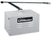
LiftMaster SW420 SW420 GL BOARD Manual - Page 14
Wiring, Power Wiring Installation - reviews
 |
View all LiftMaster SW420 manuals
Add to My Manuals
Save this manual to your list of manuals |
Page 14 highlights
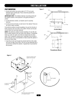
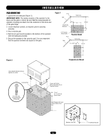
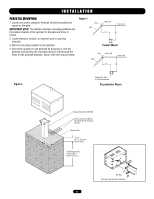
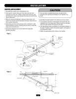
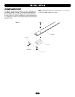
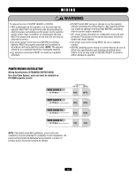
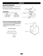
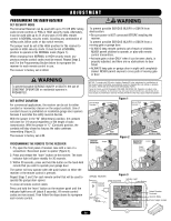
NG WWIAR RI NNGING N WARNING To reduce the risk of SEVERE INJURY or DEATH: • ANY maintenance to the operator or in the area near the operator MUST NOT be performed until disconnecting the electrical power and locking-out the power via the operator power switch. Upon completion of maintenance the area MUST be cleared and secured, at that time the unit may be returned to service. AVERTISSEMENT • Disconnect power at the fuse box BEFORE proceeding. Operator MUST be properly grounded and connected in accordance with local electrical codes. NOTE: The operator should be on a separate fused line of adequate capacity. AVERTISSEMENT • ALL electrical connections MUST be made by a qualified individual. • DO NOT install ANY wiring or attempt to run the operator without consulting the wiring diagram. We recommend that you Install an optional reversing edge BEFORE proceeding with the control station installation. • ALL power wiring should be on a dedicated circuit and well protected. The location of the power disconnect should be visible and clearly labeled. • ALL power and control wiring MUST be run in separate conduit. • BEFORE installing power wiring or control stations be sure to follow ALL specifications and warnings described below. Failure to do so may result in SEVERE INJURY to persons and/or damage to operator. ATTENTION POWER WIRING INSTALLATION Wiring SpecifiAcatiVonEs (SRTRTANIDSEDSCEOPMPEREWNIRET) On a Dual Gate System, each unit must be installed on ITS OWN separate circuits WIRE GAUGE 6 • 1/3 HP Motor ----------- SINGLE PHASE 115 Vac 230 Vac 615ft. 3077ft. WIRE GAUGE 8 • 1/3 HP Motor ----------- 432ft. 1942ft. ADVERTENCIA WIRE GAUGE 10 • 1/3 HP Motor ----------- 271ft. 1218ft. WIRE GAUGE 12 ADVERTENCIA • 1/3 HP Motor 170ft. 763ft. NOTE: Calculated using NEC guidelines. Local codes and conditions must be reviewed for suitability of wire installation. All power wiring should be dedicated and protected. Location of primary power disconnect should be labeled. 14
-
 1
1 -
2
-
3
-
4
-
5
-
6
-
7
-
8
-
 9
9 -
 10
10 -
 11
11 -
 12
12 -
 13
13 -
 14
14 -
 15
15 -
 16
16 -
 17
17 -
 18
18 -
 19
19 -
20
-
21
-
22
-
23
-
24
-
25
-
26
-
27
-
28
-
29
-
30
-
31
-
32
-
33
-
34
-
35
-
36
 |
 |
