LiftMaster SW420 SW420 S3 BOARD Manual - Page 11
Installation - model
 |
View all LiftMaster SW420 manuals
Add to My Manuals
Save this manual to your list of manuals |
Page 11 highlights
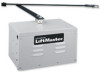
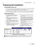
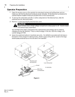
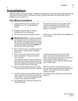
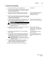
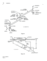
Installation 11 Installation Select the type of mounting desired. The Model is designed for post mounting as factory standard, but may either be pad mounted or pedestal mounted if provided with either the optional pad mount or pedestal mount accessory kit. Post Mount Installation 1 Locate mounting posts according to the illustration on p. 12. Locate electrical conduit. The operator cabinet may be installed either parallel or perpendicular to the fence with access cover facing away from fence (see Figure 5 or Figure 6). 2 Excavate required areas for conduit installation and mounting posts. 3 Set mounting posts and conduit in place. Knockouts for 3" pipe clamps (not supplied) are in the operator. IMPORTANT NOTE: The distance between mounting posts and the relative location of the operator to the gate and fence is critical. Be sure that the measurements for operator mounting are taken from the centerline of the fence and of the gate hinge. 4 Pour cement to secure mounting posts and allow to set for (2) days before installing power unit. 5 Knock out the post mount holes on each If mentioned holes are used, note that the end of the cabinet. There are (3) sets of upper rear holes are larger than the other holes vertically. holes. This is because a special nut is required The preferred method of post mounting is to use the (2) sets of holes nearest to the rear side of the cabinet (the side with the access for the U-Bolt in these holes due to an inaccessibility of tools inside the cabinet in the area of these holes. cover is referred to as the front side). 6 Set the operator between the posts. Allow When the posts are secured, the post tops 3" ground clearance from bottom of cabinet. should not protrude above the top flange of the operator. The operator should be level and square to the gate. 7 Insert the U-Bolt Nut (80-22754) through the A special tool is provided for this purpose (see cabinet wall from the inside and onto the leg Figure 6). of the U-Bolt. This nut can be tightened with a wrench from outside the cabinet. 8 Use standard 3/8-16 hex nuts to secure all remaining U-Bolts. Doc 01-G0610 Rev A
-
 1
1 -
2
-
3
-
4
-
5
-
 6
6 -
 7
7 -
 8
8 -
 9
9 -
 10
10 -
 11
11 -
 12
12 -
 13
13 -
 14
14 -
 15
15 -
 16
16 -
17
-
18
-
19
-
20
-
21
-
22
-
23
-
24
-
25
-
26
-
27
-
28
-
29
-
30
-
31
-
32
-
33
-
34
 |
 |
