LiftMaster SW420 SW420 S3 BOARD Manual - Page 29
Low Voltage Circuit
 |
View all LiftMaster SW420 manuals
Add to My Manuals
Save this manual to your list of manuals |
Page 29 highlights
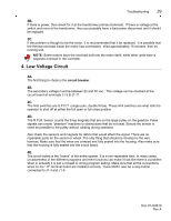
Troubleshooting 29 3B. If there is power, then check for it at the transformer primary terminals. If there is voltage at the switch and none at the transformer, then you probably have a bad power disconnect and it should be replaced. 3C. If the problem is thought to be the motor, it is recommended that it be replaced. It is possible that the thermal overload inside the motor has overheated. Wait approximately 15 minutes, then try running unit. NOTE: Some motors have the overload built into the motor itself, while other units have a separate overload in the controller. 4. Low Voltage Circuit 4A. The first thing to check is the circuit breaker. 4B. The secondary voltage must be between 22 and 30 vac. This voltage can be checked at the circuit board at terminals J1-3 & J1-11. 4C. The limit switches are S.P.D.T. (single pole, double throw). These limit switches are what tells the operator to shut off at either the full open or full close position. 4D. The R.P.M. Sensor counts the three magnets that are on the large pulley on the gearbox. False signals can create "phantom" reactions to obstructions that do not exist. Ensure the sensor is close as possible to the pulley without rubbing during operation. Also check the sensors and magnets for debris that would affect the signal. There are no repairable parts for the sensor or wheel. The only thing that should be checked is the wire harness. Make sure that the wires are crimped and fully seated into the housing. Also make sure that the housing is fully seated into the circuit board. 4E. The circuit board is the "brains" of the entire system. It is a non-repairable item. In many cases, un-awareness of the different programs and their functions can make it look like there is a problem when in actuality it is just a missed or wrong program setting. Make sure that all the connections wires on the "J1" terminal board are installed correctly. There MUST also be a stop button connected to J1-3 and J1-5. Doc 01-G0610 Rev A
-
 1
1 -
2
-
3
-
4
-
5
-
6
-
7
-
8
-
9
-
10
-
11
-
12
-
13
-
14
-
15
-
16
-
17
-
18
-
19
-
20
-
21
-
22
-
23
-
 24
24 -
 25
25 -
 26
26 -
 27
27 -
 28
28 -
 29
29 -
 30
30 -
 31
31 -
 32
32 -
 33
33 -
 34
34
 |
 |
