LiftMaster SW420 SW420 S3 BOARD Manual - Page 24
Controls and Accessory Installation
 |
View all LiftMaster SW420 manuals
Add to My Manuals
Save this manual to your list of manuals |
Page 24 highlights
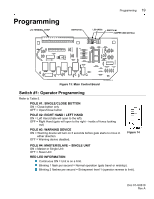
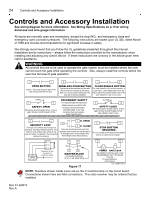
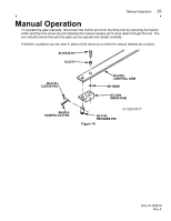
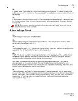
24 Controls and Accessory Installation Controls and Accessory Installation See wiring diagram for more information. See Wiring Specifications on p. 9 for wiring distances and wire gauge information. All inputs are normally open and momentary, except the stop (NC), and emergency close and emergency open (constant pressure). The following instructions are based upon UL 325, dated March of 1999 and include recommendations for significant increase in safety. We strongly recommend that you follow the UL guidelines presented throughout the manual. Installation device instructions - always follow the instructions provided by the manufacturer when installing and adjusting any control device. If these instructions are contrary to the advice given here, call for assistance. WARNING All controls that are to be used to operate the gate system must be installed where the user cannot touch the gate while operating the controls. Also, always install the controls where the user has full view of gate operation. 5 7 OPEN BUTTON Caution - Only wired devices in sight of the gate may be used with this input. 5 6 WIRELESS OPEN BUTTON Any device can be used here and the radio (R2) Is wired here internally by the factory. Note, on a second inherent obstruction, this input will not function (disabled). 5 4 CLOSE/SINGLE BUTTON OPEN 5 9 SAFETY OPEN Will reverse (close) the gate if active. If struck again during a reversal the gate will stop. SECONDARY SAFETY It is recommended that secondary safeties always be used for both the open and close directions. Use safety edges. In any case, the device must sense people. Loops cannot be used. CLOSE 5 10 SAFETY CLOSE Will reverse (open) the gate if active. If stuck again during a reversal the gate will stop. May defeat the timer to close. 5 8 SECURITY LOOP This input is for vehicles only and does not provide UL secondary safety for persons. This functions as an wireless open unless on the close limit where it is defeated - thus preventing vehicles from entering. 1 E- OPEN 3 3 5 2 E- CLOSE These are constant pressure inputs that bypasses the processor and may be used in an emergency even if the processor fails. Note left/right switch effects direction. STOP BUTTON - REQUIRED - This is a normally closed input and the operator will not run unless this is installed! 12 3 RADIO RECEIVER R1 R2 R3 TERMINAL STRIP ON SIDE OF CONTROL PANEL 24 VAC 11 12 11 12 MASTER/SLAVE Use shielded twisted pair. do not run with power wiring. Figure 17 13 14 POWER GATE LOCK USE POWER TO MATCH GATE LOCK REQUIREMENTS, NOT TO EXCEED 115V 10A. For warning devices, call the factory 01-G0610F16 NOTE: Numbers shown inside a box are on the J1 terminal strip on the circuit board. Connections shown here are field connections. The radio receiver may be ordered factory installed. Doc 01-G0610 Rev A
-
 1
1 -
2
-
3
-
4
-
5
-
6
-
7
-
8
-
9
-
10
-
11
-
12
-
13
-
14
-
15
-
16
-
17
-
18
-
 19
19 -
 20
20 -
 21
21 -
 22
22 -
 23
23 -
 24
24 -
 25
25 -
 26
26 -
 27
27 -
 28
28 -
 29
29 -
30
-
31
-
32
-
33
-
34
 |
 |