LiftMaster SW420 SW420 S3 BOARD Manual - Page 15
Control Arm Assembly
 |
View all LiftMaster SW420 manuals
Add to My Manuals
Save this manual to your list of manuals |
Page 15 highlights
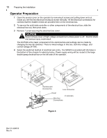
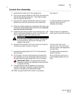
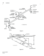
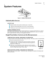
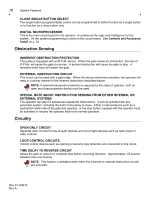
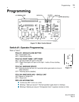
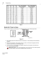
Installation 15 Control Arm Assembly 1 Assemble the control arm to the operator hub. See Figure 9. 2 Push up the manual release pin (80-2752) from below the hub and through the control arm. Then retain in place with the clevis pin (80-2753). 3 Using the 3/8" washers (80-206-65), take up any play between the clevis pin and the top of the control arm. A cotter pin (86-HP-4) keeps the clevis pin (80-2753) from vibrating out of place. 4 When the manual release pin is allowed to drop down, the control arm should swivel freely about the hub. Leave the arm free to pivot at this time. 5 Fasten the arm stop (07-2705) to the extension arm. Left Refer to Figure 9 to determine hand or right hand installations call for mounting the arm which way to mount the arm stop. stop on opposite sides of the extension arm. CAUTION If the arm stop is installed incorrectly, the gate will be prevented from opening and damage to the operator may result! 6 Assemble the extension arm to the control arm using the hardware provided as shown in Figure 9. Use the center hole in the extension arm. The other holes may be used for arm adjustment at a later time. 7 Assemble the gate bracket (10-2111) to the extension arm as shown. The gate bracket should pivot freely on the arm. 8 Put the gate in the fully closed position and extend the arm assembly out to the closed gate. Mark the point on the gate where the gate bracket will mount to the gate. Be sure that the control arm is pressed tightly against the arm stop. IMPORTANT NOTE: The gate bracket must be installed so that the arm assembly is level and able to operate smoothly. 9 The gate bracket must be installed on a structural member of the gate. If required, install a horizontal support on the gate at the appropriate height. 10 Attach the gate bracket with U-bolts or by welding. Doc 01-G0610 Rev A
-
 1
1 -
2
-
3
-
4
-
5
-
6
-
7
-
8
-
9
-
 10
10 -
 11
11 -
 12
12 -
 13
13 -
 14
14 -
 15
15 -
 16
16 -
 17
17 -
 18
18 -
 19
19 -
 20
20 -
21
-
22
-
23
-
24
-
25
-
26
-
27
-
28
-
29
-
30
-
31
-
32
-
33
-
34
 |
 |
