MSI 790FX GD70 User Guide
MSI 790FX GD70 - Motherboard - ATX Manual
 |
UPC - 816909055665
View all MSI 790FX GD70 manuals
Add to My Manuals
Save this manual to your list of manuals |
MSI 790FX GD70 manual content summary:
- MSI 790FX GD70 | User Guide - Page 1
790FX-GD70 Series MS-7577 (v1.X) Mainboard G52-75771X1 - MSI 790FX GD70 | User Guide - Page 2
's manual, please contact your place of purchase or local distributor. Alternatively, please try the following help resources for further guidance. Visit the MSI website for FAQ, technical guide, BIOS updates, driver updates, and other information: http://global.msi.com.tw/index.php? func=service - MSI 790FX GD70 | User Guide - Page 3
1. Always read the safety instructions carefully. 2. Keep this User's Manual for future reference. 3. Keep this equipment . If any of the following situations arises, get the equipment checked by a service personnel: † The power cord or plug is damaged. † Liquid has penetrated into the equipment. † - MSI 790FX GD70 | User Guide - Page 4
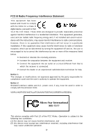
the dealer or an experienced radio/television technician for help. Notice 1 The changes or modifications not expressly approved power cord, if any, must be used in order to comply with the emission limits. VOIR LANOTICE D'INSTALLATIONAVANT DE RACCORDER AU RESEAU. Micro-Star International MS-7577 - MSI 790FX GD70 | User Guide - Page 5
WEEE (Waste Electrical and Electronic Equipment) Statement v - MSI 790FX GD70 | User Guide - Page 6
vi - MSI 790FX GD70 | User Guide - Page 7
vii - MSI 790FX GD70 | User Guide - Page 8
Support ...ii Safety Instructions Setup 2-1 Quick Components Guide 2-2 CPU (Central Processing Unit 2-3 Memory ...2-6 Power Supply ...2-8 Back Panel ...2-9 Connectors ...2-11 Button ...2-19 Slots ...2-22 LED Status Indicators 2-26 Chapter 3 BIOS Setup 3-1 Entering Setup ...3-2 The Main Menu - MSI 790FX GD70 | User Guide - Page 9
Appendix A Realtek Audio A-1 Installing the Realtek HD Audio Driver A-2 Software Configuration A-4 Hardware Setup A-19 Appendix B Overclocking Center B-1 Activating Overclocking Center B-2 System Info ...B-3 DOT ...B-5 Appendix C SB750 SATA RAID C-1 RAID Configuration C-2 Appendix D Drive - MSI 790FX GD70 | User Guide - Page 10
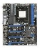
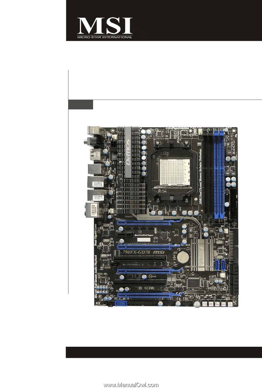
Getting Started Chapter 1 Getting Started Thank you for choosing the 790FX-GD70 Series (MS7577 v1.X) ATX motherboard. The 790FX-GD70 Series motherboards are based on AMD® 790FX & SB750 chipset for optimal system efficiency. Designed to fit the advanced AMD® Phenom II X4/ X3 and Athlon X4/ X3/ X2 AM - MSI 790FX GD70 | User Guide - Page 11
MS-7577 Mainboard Motherboard Specifications Processor Support - Supports AMD® PhenomTM II X4/ X3 and Athlon X4/ X3/ X2 processors in the AM3 package (For the latest information about CPU, please visit http://global. msi.com.tw/index.php?func=cpuform2) HyperTransport - Supports HyperTransport 3.0 up - MSI 790FX GD70 | User Guide - Page 12
& SATA8 support RAID 0/ 1 & JBOD mode by JMicron® JMB322 Floppy - 1 floppy port - Supports 1 FDD with 360 KB, 720 KB, 1.2 MB, 1.44 MB and 2.88 MB Connectors Back panel - 1 PS/2 mouse/ 1 PS/2 keyboard port - 1 Coaxial S/PDIF-out jack / 1 Optical S/PDIF-out port - 7 USB 2.0 Ports - 1 E-SATA/USB common - MSI 790FX GD70 | User Guide - Page 13
Gen. JMB362 JBAT1 BATT + AMD SB750 JMB322 IDE1 SATA7 SATA8 SATA3-4 S ATA1-2 SYSFAN2 FDD 1 JCI1 POS T_LED J COM1 I/O Chip SATA5-6 JUSB1 JUS B2 OC DRIVE J TPM1 OC GEAR J FP1 JFP2 C L R_ C M OS 1 Gr een Power RESET1 POWER1 790FX-GD70 Series (MS-7577 v1.X) ATX Motherboard 1-4 - MSI 790FX GD70 | User Guide - Page 14
Packing Checklist Getting Started MSI motherboard MSI Driver/Utility CD Back IO Shield Power Cable SATA Cable IDE/ Floppy Cable CrossFire Video Link Cable USB Bracket User's Guide * The pictures are for reference only and may vary from the packing contents of the product you purchased. - MSI 790FX GD70 | User Guide - Page 15
chapter provides you with the information about hardware setup procedures. While doing the installation, be careful in holding the components and follow the installation procedures. For some components, if you install in the wrong - MSI 790FX GD70 | User Guide - Page 16
MS-7577 Mainboard Quick Components Guide JBAT1, p.2-19 SYSFAN4, p.2-13 SYSFAN3, p.2-13 JPWM2, p.2-8 CPU, p.2-3 JCI1, p.2-13 CPUFAN1, p.2-13 DDR3, p.2-6 Back Panel, p.2-9 JPWR1, p.2-8 PCIE Slots, p.2-22 SYSFAN2, p.2-13 SYSFAN1, p.2-13 IDE1, p.2-11 JSP1, p.2-16 SATA, p.2-12 PCI Slots, p.2- - MSI 790FX GD70 | User Guide - Page 17
enhance heat dissipation. Replacing the CPU While replacing the CPU, always turn off the ATX power supply or unplug the power supply's power cord from the grounded outlet first to ensure the safety of CPU. Overclocking This motherboard is designed to support overclocking. However, please make sure - MSI 790FX GD70 | User Guide - Page 18
MS-7577 Mainboard CPU & Cooler Installation W hen you are installing the CPU, make sure the CPU has a cooler attached on the top to prevent overheating. Meanwhile, do not forget to apply some thermal paste on CPU before installing the heat sink/cooler fan for better heat dispersion. Follow the - MSI 790FX GD70 | User Guide - Page 19
Hardware Setup 5. Position the cooling set onto the retention mechanism. Hook one lift up it . 7. Fasten down the lever. 8. Attach the CPU Fan cable to the CPU fan connector on the motherboard. Important 1. Motherboard photos shown in this section are for demonstration only. The appearance of - MSI 790FX GD70 | User Guide - Page 20
MS-7577 Mainboard Memory These DIMM slots are used for installing memory modules. For more information on compatible components, please visit http://global.msi.com. tw/index.php?func=testreport DDR3 240-pin, 1.5V 72x2=144 pin 48x2=96 pin Dual-Channel Memory Population Rules In Dual-Channel mode - MSI 790FX GD70 | User Guide - Page 21
clip at each side of the DIMM slot will automatically close when the memory module is properly seated. Important You can barely see the golden finger if the memory module is properly inserted in the DIMM slot. 3. Manually check if the memory module has been locked in place by the DIMM slot clips at - MSI 790FX GD70 | User Guide - Page 22
MS-7577 Mainboard Power Supply ATX 24-pin Power Connector: JPWR1 This connector allows you to connect an ATX 24-pin power supply. To connect the ATX 24-pin power supply, make sure the plug of the power supply is inserted in the proper orientation and the pins are aligned. Then push down the power - MSI 790FX GD70 | User Guide - Page 23
Back Panel Hardware Setup Coaxial M o us e S/PDIF-Out (optional) 1394 Port LAN Keyboard S/PDIF-Out This SPDIF (Sony & Philips Digital Interconnect Format) connector is provided for digital audio transmission to external speakers through an optical fiber cable. USB Port The USB (Universal Serial - MSI 790FX GD70 | User Guide - Page 24
MS-7577 Mainboard LAN The standard RJ-45 LAN jack is for connection to Yellow . On 1000 Mbit/sec data rate is selected. Audio Ports These audio connectors are used for audio devices. You can differentiate the color of the audio jacks for different audio sound effects. Line-In (Blue) - Line In - MSI 790FX GD70 | User Guide - Page 25
Hardware Setup Connectors Floppy Disk Drive Connector: FDD1 This connector supports 360KB, 720KB, 1.2MB, 1.44MB or 2.88MB floppy disk drive. IDE Connector: IDE1 This connector supports IDE hard disk drives, to IDE device's documentation supplied by the vendors for jumper setting instructions. 2-11 - MSI 790FX GD70 | User Guide - Page 26
ATA cable into 90-degree angle. Otherwise, data loss may occur during transmission. 2. Please always use the AM D default Black SATA connectors (SATA1~6) fir s t. 3. SATA7 & SATA8 support RAID 0/ RAID 1/ JBOD function and you can set RAID mode in BIOS setup or in DRIVE BOOSTER MANAGER (refer to the - MSI 790FX GD70 | User Guide - Page 27
or consult the vendors for proper CPU cooling fan. 2. CPUFAN1 supports fan control. You can install Overclocking Center utility that will automatically control the CPU fan speed according to the actual CPU temperature. 3. Fan cooler set with 3 or 4 pins power connector are both available for CPUFAN1 - MSI 790FX GD70 | User Guide - Page 28
MS-7577 Mainboard TPM Module Connector: JTPM1 This connector connects to a TPM (Trusted Platform Module) module (optional). Please refer to the TPM security platform manual KEY 12 GND 14 GND Description 3V standby power 3.3V power Serial IRQ 5V power No pin Ground Ground Serial Port Connector: - MSI 790FX GD70 | User Guide - Page 29
Hardware Setup Front Panel Audio Connector: JAUD1 This connector allows you to connect the front panel audio and is compliant with Intel® Front Panel I/O Connectivity Design Guide. 2 10 1 9 PIN SIGNAL 1 MIC_L 2 GND 3 MIC_R 4 PRESENCE# 5 LINE out_R 6 MIC_JD 7 Front_JD 8 NC 9 - MSI 790FX GD70 | User Guide - Page 30
MS-7577 Mainboard IEEE1394 Connector: J1394_1 (optional) This connector allows you to connect the IEEE1394 device via an optional IEEE1394 bracket. Pin Definition 2 10 1 9 PIN SIGNAL PIN 1 TPA+ 2 3 Ground 4 5 TPB+ 6 7 Cable power 8 9 Key (no pin) 10 SIGNAL TPAGround TPBCable - MSI 790FX GD70 | User Guide - Page 31
Hardware Setup Front Panel Connectors: JFP1, JFP2 These connectors are for electrical connection to the front panel switches and LEDs. The JFP1 is compliant with Intel® Front Panel I/O Connectivity Design Guide. Power Power LED Switch +- JFP1 2 1 10 9 +- - + HDD Reset LED Switch JFP1 Pin - MSI 790FX GD70 | User Guide - Page 32
MS-7577 Mainboard Front USB Connector: JUSB1 / JUSB2 These connectors, compliant with Intel® I/O Connectivity Design Guide, is ideal for connecting high-speed USB interface peripherals such as USB HDD, digital cameras, MP3 players, printers, modems and the like. 2 10 1 9 Pin Definition - MSI 790FX GD70 | User Guide - Page 33
. Press the button to reset the system. Clear CMOS Button: CLR_CMOS1 There is a CMOS RAM on board that has a power supply from external battery to keep the system configuration data. With the CMOS RAM, the system can automatically boot OS every time it is turned on. If you want to clear the system - MSI 790FX GD70 | User Guide - Page 34
MS-7577 Mainboard GreenPower Button: Green Power This button is used to switch GreenPower function Important 1. Before you use OC Dial function to overclock the system. In order to increase the success rate, you should set the voltage in BIOS properly. 2. After each of the adjustments, this - MSI 790FX GD70 | User Guide - Page 35
LED message. Post Status FF Power on and first initialize CPU. C0, C1, C2 Early CPU Initialize. C4, C6 Initialize chipset. D4, D5 Initialize memory. 08 Initialize keyboard. 2A, 31 Initialize onboard devices. Load Option ROM (VGA and RAID option ROM) form BIOS to memory. 37 Displaying - MSI 790FX GD70 | User Guide - Page 36
MS-7577 Mainboard Slots PCIE (Peripheral Component Interconnect Express) Slot The PCIE slot supports the PCI Express interface expansion card. The PCIE x16 slots support up to 8.0 GB/s transfer rate. The PCIE x1 slot supports up to 250 MB/s transfer rate. PCI_E1 supports up to PCIE 2.0 x16 speed - MSI 790FX GD70 | User Guide - Page 37
an adequate power supply to the power connector on the graphics card to ensure stable operation of the graphics card. 4. Only Windows® XP with Service Pack 2 (SP2) or later & Windows® XP Profes -sional x64 Edition & Windows® Vista support the CrossFireXTM function. 5.This motherboard supports up to - MSI 790FX GD70 | User Guide - Page 38
MS-7577 Mainboard 3.W hen all of the hardware and software has been properly set up The following aspect appears in Catalyst™ Control Center: Select the Advanced View from the view drop menu. Important A CrossFireX™ system has four possible display modes: • SuperTiling • Scissor Mode • Alternate - MSI 790FX GD70 | User Guide - Page 39
Hardware Setup PCI (Peripheral Component Interconnect) Slot The PCI slot supports LAN card, SCSI card, USB card, and other add-on cards that comply with PCI specifications. 32-bit PCI Slot Important When adding or removing expansion cards, make sure that you unplug the power supply first. Meanwhile - MSI 790FX GD70 | User Guide - Page 40
MS-7577 Mainboard LED Status Indicators NB Phase LED CPU Phase LEDs Memory Phase LEDs System Phase LEDs OC Dial LED HDD Status LED NB Phase LED Lights blue when the the NB is operating. CPU Phase LEDs These LEDs indicate the current CPU power phase mode. Follow the instructions below to read. - MSI 790FX GD70 | User Guide - Page 41
Hardware Setup Memory Phase LEDs These LEDs indicate the current memory power phase mode. Follow the instructions below to read. 1 LED will light blue when memory is in 1 phase power mode. 2 LEDs will light blue when memory is in 2 phase power mode. System Phase LEDs These LEDs indicate the current - MSI 790FX GD70 | User Guide - Page 42
Chapter 3 BIOS Setup BIOS Setup This chapter provides information on the BIOS Setup program and allows you to configure the system for optimum use. You may need to run the Setup program when: ² An error message appears on the screen during the system booting up, and requests you to run SETUP. ² - MSI 790FX GD70 | User Guide - Page 43
MS-7577 Mainboard Entering Setup Power on the computer and the system will start POST (Power On Self Test) process. W hen the message below appears on the screen, press key to enter Setup. Press DEL to enter SETUP If the message disappears before you respond and you still wish to enter Setup, - MSI 790FX GD70 | User Guide - Page 44
changes General Help Enter CPU Specification submenu Enter Memroy-Z submenu Load Optimized Defaults Load Fail-Safe Defaults Save all the CMOS changes and exit Getting Help After entering the Setup menu, the first menu you will see is the Main Menu. Main Menu The main menu lists the setup functions - MSI 790FX GD70 | User Guide - Page 45
MS-7577 Mainboard The Main Menu Standard CMOS Features Use this menu for basic system configurations, such as time, date etc. Advanced BIOS Features Use this menu to setup the items of AMI® special enhanced features. Integrated Peripherals Use this menu to specify your settings for integrated - MSI 790FX GD70 | User Guide - Page 46
vendor for stable system performance. Load Optimized Defaults Use this menu to load the default values set by the motherboard manufacturer specifically for optimal performance of the motherboard. Save & Exit Setup Save changes to CMOS and exit setup. Exit Without Saving Abandon all changes and exit - MSI 790FX GD70 | User Guide - Page 47
MS-7577 Mainboard Standard CMOS Features The items in Standard CMOS Features Menu include some basic setup items. Use the arrow keys to highlight the item and then use the or keys to select the value you want in each item. Date (MM:DD:YY) This allows you to set the system to the - MSI 790FX GD70 | User Guide - Page 48
Errors] The system stops when any error is detected. The system doesn't stop for any detected error. System Information Press to enter the sub-menu, and the following screen appears. This sub-menu shows the CPU information, BIOS version and memory status of your system (read only). 3-7 - MSI 790FX GD70 | User Guide - Page 49
MS-7577 Mainboard Advanced BIOS Features BIOS Flash Protection W hen enabled, the BIOS' data cannot be changed when attempting to update the BIOS with a Flash utility. To successfully update the BIOS, you'll need to disable this Flash BIOS Protection function. You should enable this function at all - MSI 790FX GD70 | User Guide - Page 50
set the item to higher values. CPU Feature Press to enter the sub-menu and the following screen appears: SVM Support This item allows you to enable/disable the AMD SVM (Secure Virtual Machine) Tec hn ology. C1E Support To enable this item to read the CPU power consumption while idle. Not all - MSI 790FX GD70 | User Guide - Page 51
MS-7577 Mainboard 1st/ 2nd/ 3rd Boot Device The items allow you to set the first/ second/ Third boot device where BIOS attempts to load the disk operating system. Boot From Other Device Setting the option to [Yes] allows the system to try to boot from other device. if the system fails to boot from - MSI 790FX GD70 | User Guide - Page 52
whether to invoke the Boot ROM of the LAN controller. Onboard IEEE 1394 Controller This item allows you to enable/disable the onboard IEEE1394 controller. E-SATA/ HW RAID Controller This item allows you to enable/ disable the E-SATA & HW RAID controller. E-SATA Controller Mode This item allows - MSI 790FX GD70 | User Guide - Page 53
MS-7577 Mainboard Drive Booster (HW RAID) (for JMB322, SATA7~8) Press to enter the sub-menu, and the following screen appears. Current Mode This item shows the current SATA mode. Read only. Drive Booster M ode Update: Update To RAID0 (Stripe)/ RAID1 (Mirror)/ JBOD (Large)/ Normal Hdd These - MSI 790FX GD70 | User Guide - Page 54
Important S3-related functions described in this section are available only when your BIOS supports S3 sleep mode. ACPI Function This item is to activate the ACPI (Advanced Configuration and Power Management Interface) Function. If your operating system is ACPI-aware, such as W indows 2000/ XP - MSI 790FX GD70 | User Guide - Page 55
MS-7577 Mainboard Power LED When ACPI Standby State is set to [S3], this item will appear and selectable. This item is used to select the indication method of Power LED. Power Button Function This feature sets the function of the power button. Settings are: [Power On/ Off]The power button - MSI 790FX GD70 | User Guide - Page 56
W hen set to [Enabled], the feature allows your system to be awakened from the power saving modes through any event by onboard LAN. Resume By RTC Alarm This is used to enable or disable the feature of booting up the system on a scheduled time/date from the S3, S4, and S5 state. 3-15 - MSI 790FX GD70 | User Guide - Page 57
MS-7577 Mainboard H/W Monitor Chassis Intrusion The field enables or disables of the field will automatically return to [Enabled] later. CPU Smart FAN Target The motherboard provides the Smart Fan function which can control the CPU fan speed automatically depending on the current temperature to keep - MSI 790FX GD70 | User Guide - Page 58
of memory to reach the best power saving function. Motherboard LED Control This item is used to control the power phase LEDs of the motherboard. ----- GreenPower Genie----ICore/ I12V These items show the amperage of Core/ 12V. Read only. Pout/ Efficiency These items show the power consumption - MSI 790FX GD70 | User Guide - Page 59
MS-7577 Mainboard BIOS Setting Password W hen you select this function, a message as below will appear on the screen: Type the password, up to six characters in length, and press . The password typed now will replace any previously set password from CMOS memory boot and you can enter Setup - MSI 790FX GD70 | User Guide - Page 60
Cell Menu BIOS Setup Important Change these settings only if you are familiar with the chipset. Current CPU / DRAM Frequency These items show the current clocks of CPU and Memory speed. Read-only. CPU Specifications Press to enter the sub-menu and the following screen appears. This submenu - MSI 790FX GD70 | User Guide - Page 61
MS-7577 Mainboard CPU Technology Support Press to enter the sub-menu and the following screen appears. This sub-menu shows the technologies that the installed CPU supported. AMD Cool'n'Quiet The Cool'n' Quiet technology can effectively and dynamically lower CPU speed and power consumption. - MSI 790FX GD70 | User Guide - Page 62
(FSB x Ratio). Read-only. Advanced Clock Calibration This item is for overclock. Setting to [Enabled] allows you to set the CPU Ratio higher. It is available only when the processor supports this function. Auto OverClock Technology Setting this item to [Max FSB] allows the system to detect the - MSI 790FX GD70 | User Guide - Page 63
MS-7577 Mainboard Memory-Z Press to enter the sub-menu and the following screen appears. DIMM1~4 Memory SPD Information Press to enter the sub-menu and the following screen appears. This sub-menu displays the informations of installed memory. Advance DRAM Configuration Press - MSI 790FX GD70 | User Guide - Page 64
Bank Interleaving is an important parameter for improving overclocking capability of memory. It allows system to access multiple banks simultaneously. Power Down Enable This is a memory power-saving technology. W hen the system does not access memory over a period of time, it will automatically - MSI 790FX GD70 | User Guide - Page 65
MS-7577 Mainboard CPU VDD Voltage (V)/ CPU-NB VDD Voltage (V)/ CPU Voltage (V)/ CPU-NB Voltage (V)/ CPU PLL Voltage (V)/ CPU voltage of CPU, Memory and chipset. Spread Spectrum W hen the motherboard's clock generator overclocked processor to lock up. Important 1. If you do not have any EMI problem, - MSI 790FX GD70 | User Guide - Page 66
BIOS Setup Failed Overclocking Resolution This motherboard supports overclocking your system from failed overclocking... Reboot 1. Press the Power button to reboot BIOS will determine that the previous overclocking is failed and restore the default settings automatically. Please press any key to boot - MSI 790FX GD70 | User Guide - Page 67
MS-7577 Mainboard User Settings Save Settings 1/ 2/ 3/ 4 These items are used to save the settings set by yourself to CMOS. Load Settings 1/ 2/ 3/ 4 These items are available after you save your settings in Save Settings 1/ 2/ 3/ 4 items , and are used to load the settings from CMOS. 3-26 - MSI 790FX GD70 | User Guide - Page 68
directly. Update BIOS ROM chip data from selected file, which is download from official website and must be saved in the root directory of the USB/ Storage drive. It only supports particular file name, which is the official BIOS file name from us. [Boot] After allocated particular BIOS file - MSI 790FX GD70 | User Guide - Page 69
MS-7577 Mainboard Important 1. Please refer to the block diagram below about the M-Flash function. Set [BIOS Update] or [Boot] in "M-Flash function as" field Select BIOS file from the root directory of USB/ Storage drive (FAT/FAT32 format only) in "Load BIOS source file from" field Save changes and - MSI 790FX GD70 | User Guide - Page 70
a specific folder in specific USB drive/ storage drive to save BIOS file from BIOS ROM chip data. Note: it only supports FAT/ FAT32 file system drive. Save File Name as Please setup a specific name for the BIOS file, which will be saved into the USB drive/ storage drive. Note: we suggest you using - MSI 790FX GD70 | User Guide - Page 71
MS-7577 Mainboard Load Fail-Safe/ Optimized Defaults The two options on the main menu allow users to restore all of the BIOS settings to the default Fail-Safe or Optimized values. The Optimized Defaults are the default values set by the motherboard manufacturer specifically for optimal performance - MSI 790FX GD70 | User Guide - Page 72
Realtek Audio Appendix A Realtek Audio The Realtek Audio provides 10-channel DAC that simultaneously supports 7.1 sound playback and 2 channels of independent stereo sound output (multiple streaming) through the Front-Out-Left and Front-Out-Right c h an nels . A-1 - MSI 790FX GD70 | User Guide - Page 73
MS-7577 Mainboard Installing the Realtek HD Audio Driver You need to install the driver for Realtek Audio codec to function properly before you can get access to 2-, 4-, 6-, 8- channel or 7.1+2 channel audio operations. Follow the procedures described below to install the drivers for different - MSI 790FX GD70 | User Guide - Page 74
Realtek Audio 3. Click Next to install the Realtek High Definition Audio Driver. 4. Click Finish to restart the system. Click here Select this option Click here A-3 - MSI 790FX GD70 | User Guide - Page 75
MS-7577 Mainboard Software Configuration After installing the audio driver, you are able to use the 2-, 4-, 6- or 8- channel audio feature now. Click the audio icon from the system tray at the lower-right corner of the screen to activate the HD Audio Configuration. It is also available to enable the - MSI 790FX GD70 | User Guide - Page 76
to enjoy different sound experience by pulling down the arrow, totally 23 kinds of sound effect will be shown for selection. Realtek HD Audio Sound Manager also provides five popular settings "Stone Corridor", "Bathroom", "Sewer pipe", "Arena" and "Auditorium" for quick enjoyment. You may choose the - MSI 790FX GD70 | User Guide - Page 77
MS-7577 Mainboard Equalizer Selection Equalizer frees users from default settings; users may create their owned preferred settings by utilizing this tool. 10 bands of equalizer, ranging - MSI 790FX GD70 | User Guide - Page 78
you might have. By leveraging our long experience at audio field, Realtek HD Audio Sound Manager provides you certain optimized equalizer settings that are back home. Simply using the music you usually play, Karaoke mode can help you eliminate the vocal of the song or adjust the key to accommodate - MSI 790FX GD70 | User Guide - Page 79
. This feature is very helpful when 2 people are using the same computer together for different purposes. Click the button and the Mixer ToolBox menu will appear. Then check the Enable playback multi-streaming and click OK to save the setup. Important You have to plug audio device into the jacks - MSI 790FX GD70 | User Guide - Page 80
will be played from the rear panel, which is the default setting. Then you must to select the Realtek HD Audio front output from the scroll list first, and use a different program to play the second audio source (for example: use Winamp to play MP3 files). You will find that the second - MSI 790FX GD70 | User Guide - Page 81
MS-7577 Mainboard 3. Playback control Tool Mute Playback device This function is to let you freely decide which ports to output the sound. And this is essential when multistreamingplayback enabled. - Realtek HD Audio Rear Output - Realtek HD Audio Front Output Mute You may choose to mute single - MSI 790FX GD70 | User Guide - Page 82
following volume controls This is to let you freely decide which volume control items to be displayed. - Enable recording multi-streaming Important Realtek Audio allows you to record the CD, Line, Mic and Stereo Mix channels simultaneously, frees you from mixing efforts. At any given period, you - MSI 790FX GD70 | User Guide - Page 83
MS-7577 Mainboard Audio I/O In this tab, you can easily configure your multi-channel audio function and speakers. You can choose a desired multi-channel operation here. a. as your device. - If not correct, Realtek HD Audio Manager will guide you to plug the device into the correct jack. a A-12 - MSI 790FX GD70 | User Guide - Page 84
Connector Settings Click to access connector settings. Realtek Audio Disable front panel jack detection (option) Find no function on front panel jacks? Please check if front jacks on your system are so-called AC' - MSI 790FX GD70 | User Guide - Page 85
MS-7577 Mainboard S/PDIF Short for Sony/Philips Digital Interface, a standard audio file transfer format. S/PDIF allows the transfer of digital audio signals from one device to another without having to be converted first to an analog format. Maintaining the viability of a digital signal prevents - MSI 790FX GD70 | User Guide - Page 86
Realtek Audio Test Speakers You can select the speaker by clicking it to test its functionality. The one you select will light up and make testing sound. - MSI 790FX GD70 | User Guide - Page 87
MS-7577 Mainboard Microphone In this tab you may set the function of the microphone. Select the Noise Suppression to remove the possible noise during recording, or - MSI 790FX GD70 | User Guide - Page 88
Realtek Audio 3D Audio Demo In this tab you may adjust your 3D positional audio before playing 3D audio applications like gaming. You may also select different environment to choose the most suitable environment you like. A-17 - MSI 790FX GD70 | User Guide - Page 89
MS-7577 Mainboard Information In this tab it provides some information about this HD Audio Configuration utility, including Audio Driver Version, DirectX Version, Audio Controller & Audio Codec. You may also select the language of this utility by choosing from the Language list. Also there is a - MSI 790FX GD70 | User Guide - Page 90
Realtek Audio Hardware Setup Connecting the Speakers W hen you have set the Multi-Channel Audio Function mode properly in the software utility, connect your speakers to the correct phone jacks in accordance with the setting in software utility. n 2-Channel Mode - MSI 790FX GD70 | User Guide - Page 91
MS-7577 Mainboard n 4-Channel Mode for 4-Speaker Output 1 4 2 5 3 6 4-Channel Analog Audio Output 1 Line In 2 Line Out (Front channels) 3 MIC 4 Line Out (Rear channels) 5 No function 6 No function a A-20 - MSI 790FX GD70 | User Guide - Page 92
n 6-Channel Mode for 6-Speaker Output Realtek Audio 1 4 2 5 3 6 6-Channel Analog Audio Output 1 Line In 2 Line Out (Front channels) 3 MIC 4 Line Out (Rear channels) 5 Line Out (Center and Subwoofer channel) 6 No function A-21 - MSI 790FX GD70 | User Guide - Page 93
) 3 MIC 4 Line Out (Rear channels) 5 Line Out (Center and Subwoofer channel) 6 Line Out (Side channels) Important To enable 7.1 channel audio-out function on Vista operating system, you have to install the Realtek Audio Driver. Or, the motherboard will support 5.1 channel audio-out only. a A-22 - MSI 790FX GD70 | User Guide - Page 94
, the most useful and powerful utility that MSI has spent much research and efforts to develop, helps users to monitor or configure the hardware status of MSI Motherboard in windows, such as CPU clock, voltage, fan speed and temperature. Before you install the Overclocking Center, please make sure - MSI 790FX GD70 | User Guide - Page 95
MS-7577 Mainboard Activating Overclocking Center Once you have your Overclocking Center installed (locate the setup source file in the setup DVD accompanying with your motherboard, path: Utility --> MSI Utility --> Overclocking Center), it will have a short cut icon on the desktop, and a short cut - MSI 790FX GD70 | User Guide - Page 96
Overclocking Center System Info In the System Info screen, you can read the information of motherboard/ memory/ PCI. Motherboard Click Motherboard to read the information of motherboard, BIOS, installed CPU and installed graphics card. B-3 - MSI 790FX GD70 | User Guide - Page 97
MS-7577 Mainboard Memory Click Memory to read the information of each memory DIMM slot. You can select a DIMM slot you want to read from the SPD list. PCI Click PCI to read the information of devices on the motherboard. B-4 - MSI 790FX GD70 | User Guide - Page 98
DOT screen. In DOT, you can select the basic setting to reach optimal perf ormance in Novice menu or you can adjust advanced values f or overclocking in Advance menu. Novice In the Novice menu, it provides one default setting and several common settings for different environments. You may choose one - MSI 790FX GD70 | User Guide - Page 99
MS-7577 Mainboard Advance In the Advance menu, you can adjust the values for each environment setting/ default setting. Click the Cooling/ Silence/ Default/ Game/ Cinema button to enter it's setting menu. Please refer to the following descriptions to adjust the values and save them. B-6 - MSI 790FX GD70 | User Guide - Page 100
values for manual overclocking. Simply click the right side of the button which arranges an arrow sign, and a drop-down menu will appear below the button, then select a value. Click the arrow sign and the drop-down menu will appear. In the "System W arning" block, you can set the maximum CPU/ system - MSI 790FX GD70 | User Guide - Page 101
MS-7577 Mainboard After you adjust the values in setting menu, you can save it for future use. Click the Save button, and enter a name in the empty box. Then, click Save button again to save - MSI 790FX GD70 | User Guide - Page 102
SATA RAID Appendix C SB750 SATA RAID The integrated SATA host controller separately, and support RAID function for performance and reliability. SB750 SATA RAID (SATA1~6) provides support for RAID 0 (Striping), RAID 1 (Mirroring), RAID 10 (Striping & Mirroring) & RAID 5 (striping with parity). RAID - MSI 790FX GD70 | User Guide - Page 103
MS-7577 Mainboard RAID Configuration Creating and deleting RAID set and performing other RAID setting operations done in the RAID BIOS. During bootup, a screen similar to the one below will appear for about few seconds. Press to enter FastBuild utility. Important Be sure to enable the RAID - MSI 790FX GD70 | User Guide - Page 104
SB750 SATA RAID View Drives Assignments This window displays the model number, capacities and assignment of the drives physically attached to the SATA host adapter. C-3 - MSI 790FX GD70 | User Guide - Page 105
MS-7577 Mainboard Define LD (Creating RAID) The selection of the RAID configuration should be based upon factors including performance, data security, and the number of drives available. It is best to carefully consider the long-term role of the system and plan the data storage strategy. RAID sets - MSI 790FX GD70 | User Guide - Page 106
SATA RAID • Initialize logical drive, zero the disk drives. RAID 1 or 10 only. • Stripe Block Size, the default 64KB is best for most applications. RAID to save the configuration or press [Ctrl-Y] to allocate the RAID capacity manually. Important 1. The default capacity is the full capacity of the - MSI 790FX GD70 | User Guide - Page 107
MS-7577 Mainboard 6. The LD creation is done, the screen shows the LD information as below. Press ESC key to the main screen. 7. Press ESC key to exit the utility, a message "System is going to REBOOT! Are You Sure?" will display, answer "Y" to exit it and the system will reboot. C-6 - MSI 790FX GD70 | User Guide - Page 108
SB750 SATA RAID Delete LD (Deleting RAID) 1. Select "Delete LD" on the main screen. 2. Choose a LD No you want to delete and press "Del" or "Alt+D" delete the RAID set. 3. On the next screen, a message will display to inform you, press "Ctrl+Y" to delete the RAID set or other key to abort it. Press - MSI 790FX GD70 | User Guide - Page 109
follow the instruction below to make a SATA RAID driver for yourself. 1. Insert the MSI DVD into the DVD-ROM drive. 2. Click the "Browse CD" on the Setup screen. 3. Copy all the contents in the : * for Windows XP: \\ChipSet\AMD\XP\SBDrv\RAID7xx * for Windows Vista: \\ChipSet\AMD\VISTA\Packages - MSI 790FX GD70 | User Guide - Page 110
SATA RAID Installing the RAID Driver Under Windows (for Non-bootable RAID Array) 1. Insert the MSI DVD into the DVD-ROM drive. 2. The DVD will auto-run and the setup screen will appear. 3. Under the Driver tab, click on AMD chipset drivers by your need. The AMD chipset drivers includes RAID Driver - MSI 790FX GD70 | User Guide - Page 111
Drive Booster Manager Appendix D Drive Booster Manager This appendix will assist users in configuring and enabling JMB322 RAID (SATA7 & SATA8) functionality on platform. The DRIVER BOOSTER MANAGER supports RAID level 0 (striping), RAID level 1 (mirroring) and JBOD (C onc aten ate). D-1 - MSI 790FX GD70 | User Guide - Page 112
MS-7577 Mainboard Introduction DRIVER BOOSTER MANAGER offers RAID level 0 (Striping), RAID level 1 (Mirroring and Duplexing)and JBOD (Concatenate) for SATA ports (SATA7 & SATA8 ) on this motherboard. RAID 0 breaks the data into blocks which are written to separate hard drives. Spreading the hard - MSI 790FX GD70 | User Guide - Page 113
Configuration The DRIVE BOOSTER MANAGER which helps you to perform the following tasks of JMicron RAID. • Viewing SATA Drive information • Creating RAID Arrays • Deleting RAID Installing the DRIVE BOOSTER MANAGER Follow the procedures described below to install the Drive Booster Manager. 1. Insert - MSI 790FX GD70 | User Guide - Page 114
MS-7577 Mainboard View SATA Drive Information Click the "Drive Booster Information" button and the information of all hard disks will display on the right side of the window. You may click the item "Controller", you will find controller information. "Drive Booster I nf or mat i on" button Or you may - MSI 790FX GD70 | User Guide - Page 115
1 and JBOD. 1. First, you have to choose a controller, that supports 2 SATA devices with RAID mode, in the Drive Booster Information screen. "Drive Booster I nf or mat i on" button 2.Click the "Drive Booster Configuration" button, and select a RAID mode you want to create. Then click the "Apply" to - MSI 790FX GD70 | User Guide - Page 116
MS-7577 Mainboard 3. A warning message will appear to remind you that the data will be erased. Press the "Yes" if you really want to perform this creation. Important You will lose all data on the SATA drives when you perform this creation. Please ensure to back up all date in the SATA hard drives - MSI 790FX GD70 | User Guide - Page 117
Drive Booster Manager Setup Password You may set a password for a volume. Click the "Change Password", a screen will display. Please enter a new password in the "New Password" box, and enter - MSI 790FX GD70 | User Guide - Page 118
MS-7577 Mainboard Delete RAID 1. First, you have to choose a volume that you intend to delete RAID mode in the Drive Booster Information screen. 2. lose all data on the SATA drives when you perform this task. Please ensure to back up all date in the SATA hard drives before performing this task. D-8 - MSI 790FX GD70 | User Guide - Page 119
Drive Booster Manager 4. A warning will appear to inform you that the deletion is finished. Click "OK" to close the window. Event Log Click the "Event Log" button, all of the significant events will be listed. "Event Log" button D-9
-
 1
1 -
 2
2 -
 3
3 -
 4
4 -
 5
5 -
 6
6 -
 7
7 -
8
-
9
-
10
-
11
-
12
-
13
-
14
-
15
-
16
-
17
-
18
-
19
-
20
-
21
-
22
-
23
-
24
-
25
-
26
-
27
-
28
-
29
-
30
-
31
-
32
-
33
-
34
-
35
-
36
-
37
-
38
-
39
-
40
-
41
-
42
-
43
-
44
-
45
-
46
-
47
-
48
-
49
-
50
-
51
-
52
-
53
-
54
-
55
-
56
-
57
-
58
-
59
-
60
-
61
-
62
-
63
-
64
-
65
-
66
-
67
-
68
-
69
-
70
-
71
-
72
-
73
-
74
-
75
-
76
-
77
-
78
-
79
-
80
-
81
-
82
-
83
-
84
-
85
-
86
-
87
-
88
-
89
-
90
-
91
-
92
-
93
-
94
-
95
-
96
-
97
-
98
-
99
-
100
-
101
-
102
-
103
-
104
-
105
-
106
-
107
-
108
-
109
-
110
-
111
-
112
-
113
-
114
-
115
-
116
-
117
-
118
-
119
 |
 |
790FX-GD70 Series
MS-7577 (v1.X) Mainboard
G52-75771X1