MSI 790FX GD70 User Guide - Page 22
Power Supply - jpwm2
 |
UPC - 816909055665
View all MSI 790FX GD70 manuals
Add to My Manuals
Save this manual to your list of manuals |
Page 22 highlights
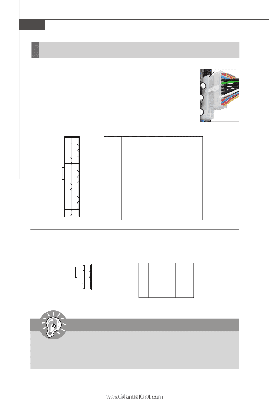
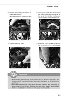
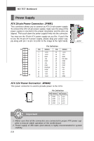
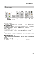
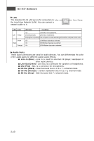
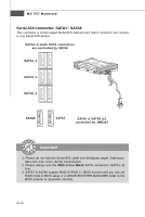
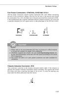
MS-7577 Mainboard Power Supply ATX 24-pin Power Connector: JPWR1 This connector allows you to connect an ATX 24-pin power supply. To connect the ATX 24-pin power supply, make sure the plug of the power supply is inserted in the proper orientation and the pins are aligned. Then push down the power supply firmly into the connector. You may use the 20-pin ATX power supply as you like. If you'd like to use the 20-pin ATX power supply, please plug your power supply along with pin 1 & pin 13 (refer to the image at the right hand). 13 1 24 12 Pin Definition PIN SIGNAL 1 +3.3V 2 +3.3V 3 GND 4 +5V 5 GND 6 +5V 7 GND 8 PW R OK 9 5VSB 10 +12V 11 +12V 12 +3.3V PIN SIGNAL 13 +3.3V 14 -12V 15 GND 16 PS-ON# 17 GND 18 GND 19 GND 20 Res 21 +5V 22 +5V 23 +5V 24 GND ATX 12V Power Connector: JPWM2 This power connector is used to provide power to the CPU. 5 1 8 4 Pin Definition PIN SIGNAL PIN SIGNAL 1 GND 2 GND 3 GND 4 GND 5 +12V 6 +12V 7 +12V 8 +12V pin 13 pin 12 Important 1. Maker sure that all the connectors are connected to proper ATX power supplies to ensure stable operation of the motherboard. 2. Power supply of 450 watts (and above) is highly recommended for system stability. 2-8
-
 1
1 -
2
-
3
-
4
-
5
-
6
-
7
-
8
-
9
-
10
-
11
-
12
-
13
-
14
-
15
-
16
-
 17
17 -
 18
18 -
 19
19 -
 20
20 -
 21
21 -
 22
22 -
 23
23 -
 24
24 -
 25
25 -
 26
26 -
 27
27 -
28
-
29
-
30
-
31
-
32
-
33
-
34
-
35
-
36
-
37
-
38
-
39
-
40
-
41
-
42
-
43
-
44
-
45
-
46
-
47
-
48
-
49
-
50
-
51
-
52
-
53
-
54
-
55
-
56
-
57
-
58
-
59
-
60
-
61
-
62
-
63
-
64
-
65
-
66
-
67
-
68
-
69
-
70
-
71
-
72
-
73
-
74
-
75
-
76
-
77
-
78
-
79
-
80
-
81
-
82
-
83
-
84
-
85
-
86
-
87
-
88
-
89
-
90
-
91
-
92
-
93
-
94
-
95
-
96
-
97
-
98
-
99
-
100
-
101
-
102
-
103
-
104
-
105
-
106
-
107
-
108
-
109
-
110
-
111
-
112
-
113
-
114
-
115
-
116
-
117
-
118
-
119
 |
 |