MSI 790FX GD70 User Guide - Page 31
Front Panel Connectors: JFP1, JFP2
 |
UPC - 816909055665
View all MSI 790FX GD70 manuals
Add to My Manuals
Save this manual to your list of manuals |
Page 31 highlights
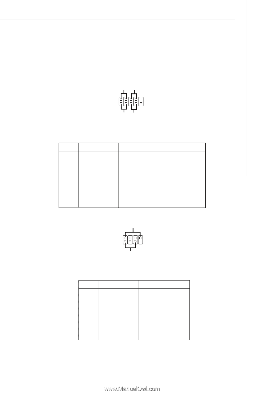
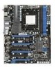
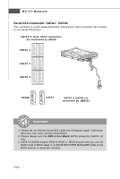
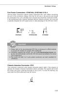
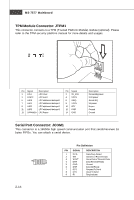
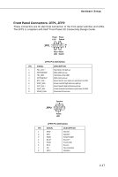
Hardware Setup Front Panel Connectors: JFP1, JFP2 These connectors are for electrical connection to the front panel switches and LEDs. The JFP1 is compliant with Intel® Front Panel I/O Connectivity Design Guide. Power Power LED Switch +- JFP1 2 1 10 9 +- - + HDD Reset LED Switch JFP1 Pin Definition PIN SIGNAL 1 HD_LED + 2 FP PW R/SLP 3 HD_LED - 4 FP PW R/SLP 5 RST_SW - 6 PW R_SW + 7 RST_SW + 8 PW R_SW - 9 RSVD_DNU DESCRIPTION Hard disk LED pull-up MSG LED pull-up Hard disk active LED MSG LED pull-up Reset Switch low reference pull-down to GND Power Switch high reference pull-up Reset Switch high reference pull-up Power Switch low reference pull-down to GND Reserved. Do not use. JFP2 Speaker - + +- 2 8 1 7 Power LED JFP2 Pin Definition PIN SIGNAL 1 GND 2 SPK- 3 SLED 4 BUZ+ 5 PLED 6 BUZ- 7 NC 8 SPK+ DESCRIPTION Ground SpeakerSuspend LED Buzzer+ Power LED BuzzerNo connection Speaker+ 2-17
-
 1
1 -
2
-
3
-
4
-
5
-
6
-
7
-
8
-
9
-
10
-
11
-
12
-
13
-
14
-
15
-
16
-
17
-
18
-
19
-
20
-
21
-
22
-
23
-
24
-
25
-
 26
26 -
 27
27 -
 28
28 -
 29
29 -
 30
30 -
 31
31 -
 32
32 -
 33
33 -
 34
34 -
 35
35 -
 36
36 -
37
-
38
-
39
-
40
-
41
-
42
-
43
-
44
-
45
-
46
-
47
-
48
-
49
-
50
-
51
-
52
-
53
-
54
-
55
-
56
-
57
-
58
-
59
-
60
-
61
-
62
-
63
-
64
-
65
-
66
-
67
-
68
-
69
-
70
-
71
-
72
-
73
-
74
-
75
-
76
-
77
-
78
-
79
-
80
-
81
-
82
-
83
-
84
-
85
-
86
-
87
-
88
-
89
-
90
-
91
-
92
-
93
-
94
-
95
-
96
-
97
-
98
-
99
-
100
-
101
-
102
-
103
-
104
-
105
-
106
-
107
-
108
-
109
-
110
-
111
-
112
-
113
-
114
-
115
-
116
-
117
-
118
-
119
 |
 |