MSI 790FX GD70 User Guide - Page 35
Debub LED: POST_LED - no post
 |
UPC - 816909055665
View all MSI 790FX GD70 manuals
Add to My Manuals
Save this manual to your list of manuals |
Page 35 highlights
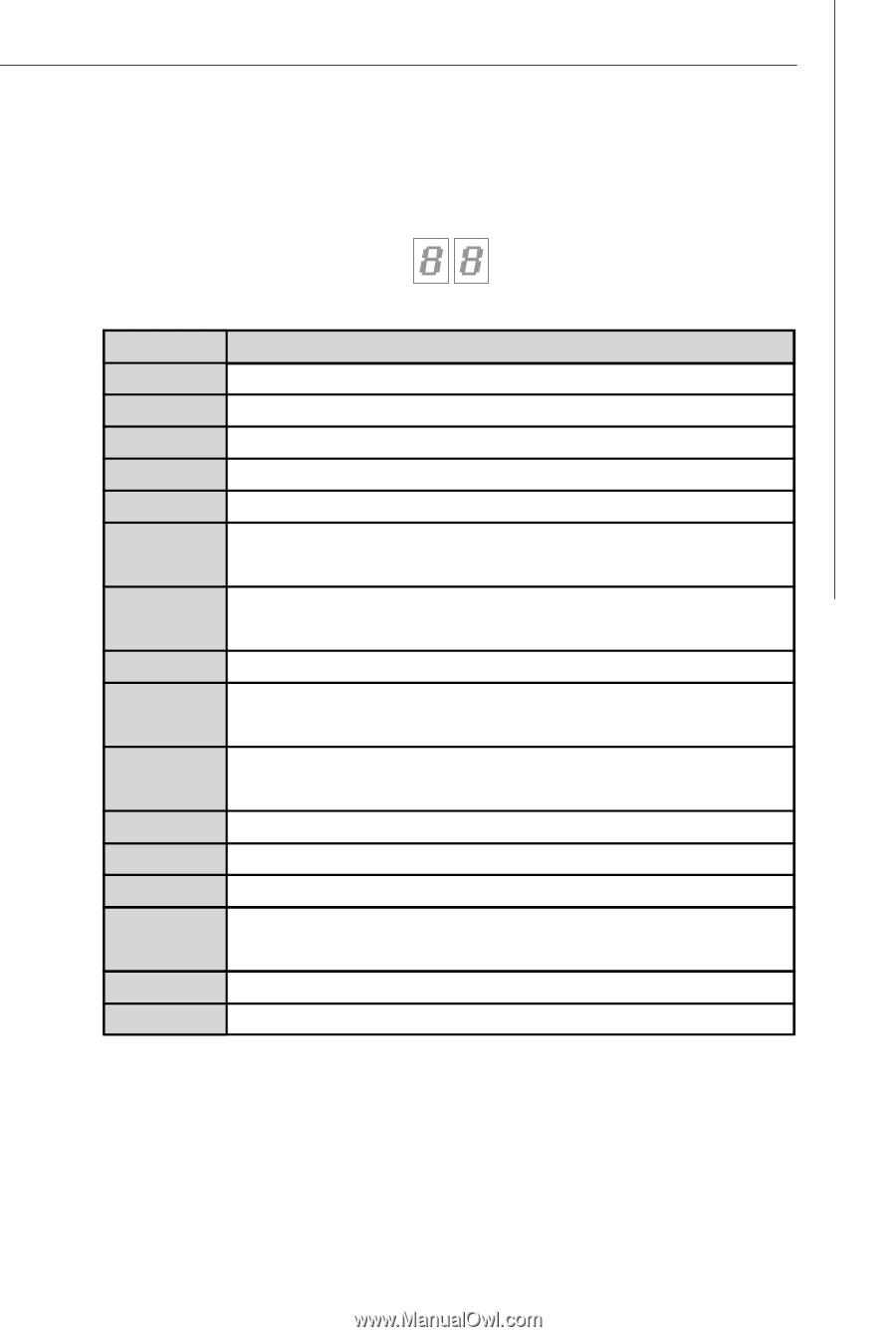
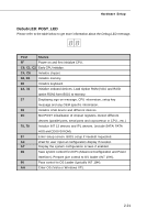
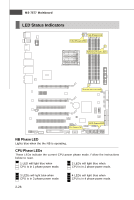
Hardware Setup Debub LED: POST_LED Please refer to the table below to get more information about the Debug LED message. Post Status FF Power on and first initialize CPU. C0, C1, C2 Early CPU Initialize. C4, C6 Initialize chipset. D4, D5 Initialize memory. 08 Initialize keyboard. 2A, 31 Initialize onboard devices. Load Option ROM (VGA and RAID option ROM) form BIOS to memory. 37 Displaying sign-on message, CPU information, setup key message and any OEM specific information. 38 Initialize USB device and different devices. 3C Mid POST initialization of chipset registers. Detect different devices (parallel ports, serial ports and coprocessor in CPU...etc.) 75, 78 Initialize INT 13 devices and IPL devices. (include SATA/ PATA HDD and CD/DVD ROM). 87 Enter setup screen. BIOS setup if needed/ requested. A4 W ait for user input at configuration display if needed. A7 Display the system configuration screen if enabled. B1 Save system context for ACPI (Advanced Configuration and Power Interface). Prepare give control to OS loader (INT 19H). 00 Pass control to OS Loader (typically INT 19H). AA Enter OS (Vista or W indows XP). 2-21
-
 1
1 -
2
-
3
-
4
-
5
-
6
-
7
-
8
-
9
-
10
-
11
-
12
-
13
-
14
-
15
-
16
-
17
-
18
-
19
-
20
-
21
-
22
-
23
-
24
-
25
-
26
-
27
-
28
-
29
-
 30
30 -
 31
31 -
 32
32 -
 33
33 -
 34
34 -
 35
35 -
 36
36 -
 37
37 -
 38
38 -
 39
39 -
 40
40 -
41
-
42
-
43
-
44
-
45
-
46
-
47
-
48
-
49
-
50
-
51
-
52
-
53
-
54
-
55
-
56
-
57
-
58
-
59
-
60
-
61
-
62
-
63
-
64
-
65
-
66
-
67
-
68
-
69
-
70
-
71
-
72
-
73
-
74
-
75
-
76
-
77
-
78
-
79
-
80
-
81
-
82
-
83
-
84
-
85
-
86
-
87
-
88
-
89
-
90
-
91
-
92
-
93
-
94
-
95
-
96
-
97
-
98
-
99
-
100
-
101
-
102
-
103
-
104
-
105
-
106
-
107
-
108
-
109
-
110
-
111
-
112
-
113
-
114
-
115
-
116
-
117
-
118
-
119
 |
 |