MSI K9N2G User Guide
MSI K9N2G - Neo-FD Motherboard - ATX Manual
 |
UPC - 816909045710
View all MSI K9N2G manuals
Add to My Manuals
Save this manual to your list of manuals |
MSI K9N2G manual content summary:
- MSI K9N2G | User Guide - Page 1
K9N2V Neo / K9N2G Neo series MS-7511 (v1.X) Mainboard G52-75111X1 i - MSI K9N2G | User Guide - Page 2
's manual, please contact your place of purchase or local distributor. Alternatively, please try the following help resources for further guidance. Visit the MSI website for FAQ, technical guide, BIOS updates, driver updates, and other information: http://global.msi.com.tw/index.php? func=service - MSI K9N2G | User Guide - Page 3
1. Always read the safety instructions carefully. 2. Keep this User's Manual for future reference. 3. Keep this . 11. If any of the following situations arises, get the equipment checked by a service personnel: † The power cord or plug is damaged. † Liquid has penetrated into the equipment - MSI K9N2G | User Guide - Page 4
if not installed and used in accordance with the instructions, may cause harmful interference to radio communications. However, limits. VOIR LANOTICE D'INSTALLATIONAVANT DE RACCORDER AU RESEAU. Micro-Star International MS-7511 This device complies with Part 15 of the FCC Rules. Operation is subject - MSI K9N2G | User Guide - Page 5
WEEE (Waste Electrical and Electronic Equipment) Statement v - MSI K9N2G | User Guide - Page 6
vi - MSI K9N2G | User Guide - Page 7
vii - MSI K9N2G | User Guide - Page 8
Revision History ...ii Technical Support ...ii Safety Instructions ...iii FCC-B Radio Frequency 2. Hardware Setup 2-1 Quick Components Guide 2-2 CPU (Central Processing Unit 2-3 Memory 23 BIOS Setting Password 3-24 Appendix A Realtek ALC888 Audio A-1 Installing the Realtek HD Audio Driver A-2 - MSI K9N2G | User Guide - Page 9
RAID Configuration B-3 Installing Driver ...B-7 NVIDIA RAID Utility Installation B-8 Using the NVMediaShield Software B-11 Appendix C Dual Core Center C-1 Activating Dual Core Center C-2 Main ...C-3 DOT (Dynamic OverClocking C-5 Clock ...C-6 Voltage ...C-7 FAN Speed ...C-8 - MSI K9N2G | User Guide - Page 10
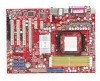
Getting Started Chapter 1 Getting Started Thank you for choosing the K9N2V Neo / K9N2G Neo Series (MS-7511 v1.X) ATX mainboard. The K9N2V Neo / K9N2G Neo Series mainboards are based on NVIDIA GeForce 8100 / GeForce 8200 chipset for optimal system efficiency. Designed to fit the advanced AM D Athlon - MSI K9N2G | User Guide - Page 11
MS-7511 Mainboard Mainboard Specifications Processor Support - AMD® Phenom/ Athlon 64/ Sempron series processors in AM2/AM2+ package - Supports 4 pin CPU Fan Pin-Header with Fan Speed Control (For the latest information about CPU Spec IDE - 1 IDE port by GeForce 8100 / GeForce 8200 - Supports Ultra - MSI K9N2G | User Guide - Page 12
connector - 1 Front Panel Audio pinheader - 1 Chassis Intrusion Switch pinheader - 1 Serial port connector Slots - 1 PCI Express x16 slot - 2 PCI Express x1 slots - 3 PCI slots - Support 3.3V/ 5V PCI bus Interface Form Factor - ATX (30.5cm X 22.0cm) Mounting - 6 mounting holes Getting Started 1-3 - MSI K9N2G | User Guide - Page 13
MS-7511 Mainboard Mainboard Layout Top : mouse Bottom: keyboard Top : Parallel Port Bo t to m : DVI SATA3 BAT T + SATA1 SATA4 JAUD1 CD_IN1 JSPD1 JUSB1 JUSB3 FDD1 J1394_1 J1394_2 K9N2V Neo / K9N2G Neo Series (MS-7511 v1.X) ATX Mainboard 1-4 JUSB2 J CI 1 SATA5 JVBAT1 JFP1 SATA6 JFP2 - MSI K9N2G | User Guide - Page 14
Packing Checklist Getting Started MSI motherboard MSI Driver/Utility CD SATA Cable Power Cable Standard Cable for IDE Devices Back IO Shield User's Guide * The pictures are for reference only and may vary from the packing contents of the product you purchased. 1-5 - MSI K9N2G | User Guide - Page 15
Hardware Setup Chapter 2 Hardware Setup This chapter provides you with the information about hardware setup procedures. While doing the installation, be careful in holding the components and follow the installation procedures. For some components, if you install in the wrong orientation, the - MSI K9N2G | User Guide - Page 16
MS-7511 Mainboard Quick Components Guide PWR1, p.2-8 CPU, p.2-3 DDR2, p.2-6 Back Panel I/O, p.2-9 IDE1, p.2-11 CPUFAN1, p.2-13 JIR1, p.2-18 PCIE Slots, p.2-21 JCOM1, p.2-15 PCI Slots, p.2-23 JAUD1, p.2-17 FDD1, p.2-11 JSPD1, p.2-17 CD_IN1, p.2-16 - MSI K9N2G | User Guide - Page 17
the CPU cooler, consult your dealer before turning on the computer. For the latest information about CPU, please visit http://global.msi.com. grounded outlet first to ensure the safety of CPU. Overclocking This mainboard is designed to support overclocking. However, please make sure your components - MSI K9N2G | User Guide - Page 18
MS-7511 Mainboard CPU Installation Procedures for Socket AM2 1. Please turn off the power and unplug the power cord before installing the CPU. 2. Pull the lever sideways away from the socket. Make sure to raise the lever up to a 90-degree angle. Sliding Plate Open Lever 90 degree 3. - MSI K9N2G | User Guide - Page 19
on the top of the retention mechanism. Locate the Fix Lever and lift up it . Fixed Lever 3. Fasten down the lever. 4. Attach the CPU Fan cable to the CPU fan connector on the mainboard. * While disconnecting the Safety Hook from the fixed bolt, it is necessary to keep an eye on your - MSI K9N2G | User Guide - Page 20
MS-7511 Mainboard Memory These DIMM slots are used for installing memory modules. For more information on compatible components, please visit http://global.msi.com. tw/index.php?func=testreport DDR2 240-pin, 1.8V 56x2=112 pin 64x2=128 pin Dual-Channel Memory Population Rules In Dual-Channel mode - MSI K9N2G | User Guide - Page 21
Hardware Setup Installing memory Modules 1. The memory module has only one notch on the center and will only fit in the right orientation. 2. Insert the memory module vertically into the DIMM slot. Then push it in until the golden finger on the memory module is deeply inserted in the DIMM slot. - MSI K9N2G | User Guide - Page 22
MS-7511 Mainboard Power Supply ATX 24-Pin Power Connector: ATX1 This connector 13 pin 12 ATX 12V Power Connector: PWR1 This 12V power connector JPW 1 is used to provide power to the CPU. PWR1 1 2 4 3 JPW1 Pin Definition PIN SIGNAL 1 GND 2 GND 3 12V 4 12V Important 1. Maker sure - MSI K9N2G | User Guide - Page 23
Parallel Port A parallel port is a standard printer port that supports Enhanced Parallel Port (EPP) and Extended Capabilities Parallel Port (ECP the cable is properly connected to your monitor (refer to your monitor manual for more information.) VGA Port The DB15-pin female connector is provided - MSI K9N2G | User Guide - Page 24
MS-7511 Mainboard Audio Ports These audio connectors are used for audio devices. You can differentiate the color of the audio jacks for different audio sound effects. - MSI K9N2G | User Guide - Page 25
1.2MB, 1.44MB or 2.88MB floppy disk drive. FDD1 IDE Connector: IDE1 This connector supports IDE hard disk drives, optical disk drives and other IDE devices. IDE1 Important If you install jumpers. Refer to IDE device's documentation supplied by the vendors for jumper setting instructions. 2-11 - MSI K9N2G | User Guide - Page 26
MS-7511 Mainboard Serial ATA Connector: SATA1~6 This connector is a high-speed when SATA connectors running in IDE mode, the SATA5 and SATA6 will be unavailable. (please refer to Chapter3 BIOS Setup -> Integrated Peripherals -> RAID Mode) SATA3 SATA2 SATA5 SATA1 SATA6 SATA4 SATA 5 a nd SATA6 - MSI K9N2G | User Guide - Page 27
Important 1. Please refer to the recommended CPU fans at processor's official website or consult the vendors for proper CPU cooling fan. 2. CPUFAN1 supports fan control. You can install Dual screen. To clear the warning, you must enter the BIOS utility and clear the record. 1 CINTRU 2 GND JCI1 2-13 - MSI K9N2G | User Guide - Page 28
MS-7511 Mainboard Front USB Connector: JUSB1, JUSB2, JUSB3 This connector, compliant with Intel® I/O Connectivity Design Guide, is ideal for connecting high-speed USB interface peripherals such as USB HDD, digital cameras, MP3 players, printers, modems and the like. 2 10 1 9 JUSB1~3 Pin - MSI K9N2G | User Guide - Page 29
Hardware Setup IEEE1394 Connector: J1394_1, J1394_2(optional) This connector allows you to connect the IEEE1394 device via an optional IEEE1394 bracket. 2 10 1 9 J1394_1~2 (The 1394 connector is in Green color.) Pin Definition PIN SIGNAL PIN 1 TPA+ 2 3 Ground 4 5 TPB+ 6 7 Cable - MSI K9N2G | User Guide - Page 30
MS-7511 Mainboard Front Panel Connectors: JFP1, JFP2 These connectors are for electrical connection to the front panel switches and LEDs. The JFP1 is compliant with Intel® Front Panel I/O Connectivity Design Guide. JFP1 10 Power Switch + Power LED 2 9 + Reset - Switch - HDD 1 +LED JFP2 +8 7 - MSI K9N2G | User Guide - Page 31
JAUD1 This connector allows you to connect the front panel audio and is compliant with Intel® Front Panel I/O Connectivity Design Guide. 2 1 10 9 JAUD1 PIN SIGNAL 1 MIC_L 2 GND 3 MIC_R 4 PRESENCE# 5 LINE out_R 6 MIC_JD 7 Front_JD 8 NC 9 LINE out_L 10 LINEout_JD HD Audio Pin - MSI K9N2G | User Guide - Page 32
MS-7511 Mainboard Infrared Module Connector: JIR1 This connector allows you to connect to infrared module and is compliant with Intel® Front Panel I/O Connectivity Design Guide. You must configure the setting through the BIOS refer to the TPM security platform manual for more details and usages. 2 - MSI K9N2G | User Guide - Page 33
which integrates four LEDs and USB ports. It allows users to identify system problems through 16 various combinations of LED signals. D-Bracket™ 2 (Optional) 1 CPU clock, 3 4 checking type ofvideo onboard. Then, detect and initializethe video adapter. 1 2 EarlyChipset Initialization 3 4 BIOS - MSI K9N2G | User Guide - Page 34
MS-7511 Mainboard Jumper Clear CMOS Jumper: JBAT1 There is a CMOS RAM onboard that has a power supply from an external battery to keep the data of system - MSI K9N2G | User Guide - Page 35
K9N2G Neo supports Hybird SLI Technology, K9N2V Neo does not support this feature. System Request 1. Hybrid SLI is only supported for the motherboard GPU 3. For best HybridPower benefits, the following minimum system configuration is recommended: - AMD Athlon X2 3800+ CPU or Intel CPU running at - MSI K9N2G | User Guide - Page 36
MS-7511 Mainboard Enabling Hybrid SLI Technology Power off the system and install the NVIDIA SLI graphic card that supports Hybrid SLI technology. After then, power on the system and install the driver that Hybrid SLI technology. Restart the system and wait for the Hybrid Icon to show in the System - MSI K9N2G | User Guide - Page 37
Hardware Setup PCI (Peripheral Component Interconnect) Slots The PCI slots support LAN cards, SCSI cards, USB cards, and other add or software settings for the expansion card, such as jumpers, switches or BIOS configuration. PCI Interrupt Request Routing The IRQ, acronym of interrupt request line - MSI K9N2G | User Guide - Page 38
This chapter provides information on the BIOS Setup program and allows you to configure the system for optimum use. You may need to run the Setup program when: ² An error message appears - MSI K9N2G | User Guide - Page 39
MS-7511 Mainboard Entering Setup Power on the computer and the system will start POST , and keys. Important 1. The items under each BIOS category described in this chapter are under continuous update for better system performance. Therefore, the description may be slightly different - MSI K9N2G | User Guide - Page 40
BIOS Setup Control Keys Enter> Move to the sub-menu. If you want to return to the main menu, just press the . General Help The BIOS setup program provides a General Help screen. You can call up this screen from any menu by simply pressing . The - MSI K9N2G | User Guide - Page 41
MS-7511 Mainboard The Main Menu Standard CMOS Features Use this menu for basic system configurations, such as time, date etc. Advanced BIOS Features Use for power management. PNP/PCI Configurations This entry appears if your system supports PnP/PCI. H/W Monitor This entry shows your PC health status. - MSI K9N2G | User Guide - Page 42
BIOS Setting Password Use this menu to set the password for BIOS. Save & Exit Setup Save changes to CMOS and exit setup. Exit Without Saving Abandon all changes and exit setup. BIOS Setup 3-5 - MSI K9N2G | User Guide - Page 43
MS-7511 Mainboard Standard CMOS Features The items in Standard CMOS Features Menu includes The format is . day Day of the week, from Sun to Sat, determined by BIOS. Read-only. month The month from Jan. through Dec. date The date from 1 to 31 can be keyed by numeric - MSI K9N2G | User Guide - Page 44
BIOS Setup Device/ Vender/ Size It will showing the device information that you connected to the IDE/SATA connector. LBA/Large M ode This allows you to enable or disable the LBA Mode. Setting to Auto enables LBA mode if the device supports it and the devices is not already formatted with LBA mode - MSI K9N2G | User Guide - Page 45
MS-7511 Mainboard System Information Press to enter the sub-menu, and the following screen appears. CPU Infromation/ BIOS Version/ M emory Information These items show the CPU information, BIOS version and memory status of your system (read only). 3-8 - MSI K9N2G | User Guide - Page 46
Advanced BIOS Features BIOS Setup Full APIC (Advanced Programmable Interrupt Controller). Due to compliance with PC2001 design guide, the system is able to run in APIC mode. Enabling . You need to select the MPS version supported by your operating system. To find out which version to use, consult - MSI K9N2G | User Guide - Page 47
MS-7511 Mainboard values. CPU Feature Press to enter the sub-menu and the following screen appears: SVM Support This setting allows you to enable/disable the SVM support. size shared to the VGA card. Hybird SLI support If you need to enable this option, must use more than 2GB of - MSI K9N2G | User Guide - Page 48
allow you to set the sequence of boot devices where BIOS attempts to load the disk operating system. Boot From Other Computing Press to enter the sub-menu and the following screen appears: TCG/TPM SUPPORT This setting allows you to enable/disable the TCG/TPM. TPM Enable/Disable Status This - MSI K9N2G | User Guide - Page 49
MS-7511 Mainboard Integrated Peripherals USB Controller This setting allows you to enable/disable the onboard USB 1.1/ 2.0 controller. USB Device Legacy Support Select [Enabled] if you need to use a USB-interfaced device in the operating system. Onboard LAN Controller This setting allows you to - MSI K9N2G | User Guide - Page 50
or disable the IDE controller. PCI IDE BusMaster This item allows you to enable/ disable BIOS to used PCI busmastering for reading/ writing to IDE drives. OnChip SATA Controller This item [ECP + EPP] will allow the onboard parallel port to support both the ECP and EPP modes simultaneously. 3-13 - MSI K9N2G | User Guide - Page 51
MS-7511 Mainboard Power Management Setup Important S3-related functions described in this section are available only when your BIOS supports S3 sleep mode. ACPI Function This item is to activate the ACPI (Advanced Configuration and Power Management Interface) Function. If your operating system is - MSI K9N2G | User Guide - Page 52
BIOS Setup Power Button Function This feature sets the function of the power button. Settings are: [Power On/ Off] The power button functions as normal power - MSI K9N2G | User Guide - Page 53
MS-7511 Mainboard PnP/PCI Configurations This section describes configuring the PCI bus system and PnP (Plug & Play) feature. PCI, or Peripheral Component Interconnect, is a system which allows I/O devices to operate at speeds nearing the speed the CPU itself uses when communicating with its special - MSI K9N2G | User Guide - Page 54
H/W Monitor BIOS Setup Chassis Intrusion The field enables or disables the feature the field to [Reset]. The setting of the field will automatically return to [Enabled] later. CPU Smart FAN Target The mainboard provides the Smart Fan system which can control the fan speed automatically depending - MSI K9N2G | User Guide - Page 55
MS-7511 Mainboard Cell Menu Important Change these settings only if you are familiar with the chipset. Current CPU/ DRAM Frequency These items show the current clocks of CPU and Memory speed. Read-only. D.O.T. Control D.O.T. (Dynamic Overclocking Technology) is the automatic overclocking function, - MSI K9N2G | User Guide - Page 56
more stable than manual overclocking, basically, it is still risky. We suggest user to make sure that your CPU can afford to CPU speed and power consumption. Important To ensure that Cool'n'Quiet function is activated and will be working properly, it is required to double confirm that: 1. Run BIOS - MSI K9N2G | User Guide - Page 57
MS-7511 Mainboard Adjust CPU FSB Frequency This item allows you to select the CPU Front Side Bus clock frequency (in MHz). Adjust CPU Ratio This item is used to adjust CPU clock multiplier (ratio). It is available only when the processor supports Timing Mode sets to [Manual], this field is adjustable - MSI K9N2G | User Guide - Page 58
BIOS Setup allowed to precharge. If insufficient time is allowed for the RAS detect all of the DRAM timing. SB to CPU Freq Auto [Enabled] Auto Detect HT frequency. [Disabled] Manual to setting HT frequency. SB to CPU Frequency W hen the SB to CPU Freq Auto set to [Disabled], the item will - MSI K9N2G | User Guide - Page 59
MS-7511 Mainboard Spread Spectrum Configuration Press to enter the sub-menu and the following screen appears. CPU/LDT Spread Spectrum This setting is used to enable or disable the CPU/LDT (HT Bus multiplier) Spread Spectrum feature. PCIE Spread Spectrum This setting is used to enable or - MSI K9N2G | User Guide - Page 60
set by the mainboard manufacturer specifically for optimal performance of the mainboard. The Fail-Safe Defaults are the default values set by the BIOS vendor for stable system performance. W hen you select Load Fail-Safe Defaults, a message as below appears: Selecting [Ok] and pressing Enter loads - MSI K9N2G | User Guide - Page 61
MS-7511 Mainboard BIOS Setting Password W hen you select this function, a message as below will appear on the screen: Type the password, up to six characters in length, and - MSI K9N2G | User Guide - Page 62
Realtek ALC888 Audio Appendix A Realtek ALC888 Audio The Realtek ALC888 provides 10-channel DAC that simultaneously supports 7.1 sound playback and 2 channels of independent stereo sound output (multiple streaming) through the Front-Out-Left and Front-OutRight channels. A-1 - MSI K9N2G | User Guide - Page 63
® 2000, you must install W indows® 2000 Service Pack4 or later before installing the driver. For Windows® XP, you must install W indows® XP Service Pack1 or later before installing the driver. The following illustrations are based on W indows® XP environment and could look slightly different if you - MSI K9N2G | User Guide - Page 64
Realtek ALC888 Audio 3. Click Next to install the Realtek High Definition Audio Driver. 4. Click Finish to restart the system. Click here Select this option Click here A-3 - MSI K9N2G | User Guide - Page 65
MS-7511 Mainboard Software Configuration After installing the audio driver, you are able to use the 2-, 4-, 6- or 8- channel audio feature now. Click the audio icon from the system tray at the lower-right corner of - MSI K9N2G | User Guide - Page 66
Realtek ALC888 Audio Sound Effect Here you can select a sound effect you like from the Environment list. Environment Simulation You will be able to enjoy different sound experience by pulling down the arrow, several kinds of sound effect will be shown for selection. Realtek HD Audio Sound Manager - MSI K9N2G | User Guide - Page 67
MS-7511 Mainboard Equalizer Selection Equalizer frees users from default settings; users may create their owned preferred settings by utilizing this tool. 10 bands of equalizer, ranging - MSI K9N2G | User Guide - Page 68
Realtek ALC888 Audio Frequently Used Equalizer Setting Realtek recognizes the needs that you might have. By leveraging our long experience at audio field, Realtek HD Audio Sound Manager provides you certain optimized equalizer settings that are frequently used for your quick enjoyment. [How to Use - MSI K9N2G | User Guide - Page 69
MS-7511 Mainboard Mixer In the Mixer part, you may adjust the volumes of the rear after you pluging the speakers into the jacks on the front panel. 2. Multi-Stream Function ALC888 supports an outstanding feature called Multi-Stream, which means you may play different audio sources simultaneously and - MSI K9N2G | User Guide - Page 70
Realtek ALC888 Audio W hen you are playing the first audio source (for example: use W indows Media Player to play DVD/VCD), the output will be played from the rear panel, which is the default setting. Then you must to select the Realtek HD Audio front output from the scroll list first, and use a - MSI K9N2G | User Guide - Page 71
MS-7511 Mainboard 3. Playback control Tool Mute Playback device This function is to let you freely decide which ports to output the sound. And this is essential - MSI K9N2G | User Guide - Page 72
4. Recording control Realtek ALC888 Audio Tool Mute Recording device -Back Line in/Mic, Front Lin in -Realtek HD Audio Input Mute You may choose to mute single or multiple volume controls or to completely mute sound input. Tool - Show the following volume controls This is to let you freely - MSI K9N2G | User Guide - Page 73
MS-7511 Mainboard Audio I/O In this tab, you can easily configure your multi-channel audio function and speakers. You can choose a desired jack changed to the one that is same as your device. - If not correct, Realtek HD Audio Manager will guide you to plug the device into the correct jack. A-12 - MSI K9N2G | User Guide - Page 74
Connector Settings Click to access connector settings. Realtek ALC888 Audio Disable front panel jack detection (option) Find no function on front panel jacks? Please check if front jacks on your system are so-called AC'97 jacks. If so, please check this item to disable front panel jack detection - MSI K9N2G | User Guide - Page 75
MS-7511 Mainboard S/PDIF Short for Sony/Philips Digital Interface, a standard audio file transfer format. S/PDIF allows the transfer of digital audio signals from one device to - MSI K9N2G | User Guide - Page 76
Realtek ALC888 Audio Test Speakers You can select the speaker by clicking it to test its functionality. The one you select will light up and make testing sound. If any speaker fails to make sound, then check whether the cable is inserted firmly to the connector or replace the bad speakers with - MSI K9N2G | User Guide - Page 77
MS-7511 Mainboard Microphone In this tab you may set the function of the microphone. Select the Noise Suppression to remove the possible noise during recording, or - MSI K9N2G | User Guide - Page 78
Realtek ALC888 Audio 3D Audio Demo In this tab you may adjust your 3D positional audio before playing 3D audio applications like gaming. You may also select different environment to choose the most suitable environment you like. A-17 - MSI K9N2G | User Guide - Page 79
MS-7511 Mainboard Information In this tab it provides some information about this HD Audio Configuration utility, including Audio Driver Version, DirectX Version, Audio Controller & Audio Codec. You may also select the language of this utility by choosing from the Language list. Also there is a - MSI K9N2G | User Guide - Page 80
Realtek ALC888 Audio Hardware Setup Connecting the Speakers W hen you have set the Multi-Channel Audio Function mode properly in the software utility, connect your speakers to the correct phone jacks in accordance with the setting in software utility. n 2-Channel Mode for Stereo-Speaker Output 1 4 - MSI K9N2G | User Guide - Page 81
MS-7511 Mainboard n 4-Channel Mode for 4-Speaker Output 1 4 2 5 3 6 1 Line In 2 Line Out (Front channels) 3 MIC 4 Line Out (Rear channels) 5 No function 6 No function A-20 - MSI K9N2G | User Guide - Page 82
Realtek ALC888 Audio n 6-Channel Mode for 6-Speaker Output 1 4 2 5 3 6 1 Line In 2 Line Out (Front channels) 3 MIC 4 Line Out (Rear channels) 5 Line Out (Center and Subwoofer channel) 6 No function A-21 - MSI K9N2G | User Guide - Page 83
MS-7511 Mainboard n 8-Channel Mode for 8-Speaker Output 1 4 2 5 3 6 1 Line In 2 Line Out (Front channels) 3 MIC 4 Line Out (Rear channel audio-out function on Vista operating system, you have to install the Realtek Audio Driver. Or, the mainboard will support 5.1 channel audio-out only. A-22 - MSI K9N2G | User Guide - Page 84
Appendix B nVidia RAID nVidia RAID NVIDIA brings Redundant Array of Independent Disks (RAID) technology-which is used by the world's leading businesses-to the common PC desktop. This tech- nology uses multiple drives to either increase total disk space or to offer data protection. For all levels, - MSI K9N2G | User Guide - Page 85
MS-7511 Mainboard Introduction System Requirement Operating System Support NVRAID supports the following operating systems: W indows XP, W indows Vista RAID Arrays NVRAID supports the following types of RAID arrays described in this section: RAID 0: RAID 0 defines a disk striping scheme that - MSI K9N2G | User Guide - Page 86
array. 3. Boot from the W indows CD, use the floppy disk that has the RAID driver to copy and install the nForce RAID software. (Check p.B-7 for details.) 4. Initialize the NVRAID Array Disks. Setting Up the NVRAID BIOS Be sure to enable the RAID function in SATA Channel of Integrated Peripherals in - MSI K9N2G | User Guide - Page 87
MS-7511 Mainboard Understanding the "Define a New Array" Window Use the Define a New Array window to • Select the RAID Mode • Set up the Striping Block • Specify which - MSI K9N2G | User Guide - Page 88
], which is 32KB, but the values can be between [4 KB] and [128 KB]. • Assigning the Disks The disks that you enabled from the RAID Config BIOS setup page appear in the Free Disks block. These are the drives that are available for use as RAID array disks. To designate a free disk - MSI K9N2G | User Guide - Page 89
MS-7511 Mainboard Completing the RAID BIOS as RAID drives. The Array List window appears, where you can review the RAID arrays that you have set up. 3. Use the arrow setup has been configured from the RAID BIOS, the next step is to configure and load NVRAID drivers under W indows, as explained in " - MSI K9N2G | User Guide - Page 90
available NVRAID Adapaters. Important Please follow the instruction below to make an "NVIDIA RAID Driver" for yourself. 1. Insert the MSI CD into the CD-ROM drive. 2. XP installation is completed, then take out the floppy. 9. Follow the instructions on how to install W indows XP. After W indows XP - MSI K9N2G | User Guide - Page 91
MS-7511 Mainboard NVIDIA RAID Utility Installation Installing the NVIDIA MediaShield Software Under Windows (for Non-bootable RAID Array) The existing W indows Serial ATA driver must be upgraded to use the NVIDIA Serial ATA driver. This section describes how to run the setup application and install - MSI K9N2G | User Guide - Page 92
nVidia RAID Initializing and Using the Disk Array The RAID array is now ready to be initialized under W indows. 1. Launch Computer Management by clicking "Start" --> "Settings" --> "Control Panel" then open the "Administrative Tools" folder and double click on "Computer Management". 2. Click "Disk - MSI K9N2G | User Guide - Page 93
MS-7511 Mainboard 5. Check the disk in the list if you want to make the array a dynamic disk, then click Next. The Completing the Initialize and Convert - MSI K9N2G | User Guide - Page 94
nVidia RAID Using the NVMediaShield Software Accessing the Storage Page To access the NVIDIA Control Panel Storage page: 1. Click Star-> Programs-> NVIDIA Corporation-> NVIDIA Control Panel-> Storage. 2. The NVIDIA Control Panel - Storage page appears. B-11 - MSI K9N2G | User Guide - Page 95
MS-7511 Mainboard Using the Storage Page From the Storage page, you can accomplish the following tasks: and RAID 5. Click Synchronize array to start the Synchronize Array W izard and then follow instructions. You can press F1 to access the online help that walks you through the W izard with step-by- - MSI K9N2G | User Guide - Page 96
5 array2. The spare drive can take over for a failed disk. MediaShield RAID supports two types of spare drives: Free Disk A free disk is a disk that is spare disk for that array. Instructions Click Designate spare to start the Designate Spare W izard and then follow instructions. You can press F1 to - MSI K9N2G | User Guide - Page 97
MS-7511 Mainboard Remove a Spare The Remove spare option appears only if you have a a RAID array with a spare disk allocated to it. Click Remove spare to start the Remove Spare W izard and then follow the instructions Your disks must be partitioned using the GUID partition table (GPT) if you plan to - MSI K9N2G | User Guide - Page 98
Not a valid combination ** m >= (n/2 + 1) m >= n - 1 ** Not a valid combination ** m >= 2 x (n -1) ; where m is an even number of disks. m >= n Instructions Click Migrate array to start the Migrate Array W izard and then follow instructions. You can press F1 to access the online help that walks you - MSI K9N2G | User Guide - Page 99
MS-7511 Mainboard View Storage Information • You can use the Storage page to view the Array W izard-from the list of links in the Related tasks section of the side menu. Instructions Click View Storage Configuration to open the associated page. The View Storage Configuration page provides the - MSI K9N2G | User Guide - Page 100
Mainboard & MSI Graphics card in windows, such as CPU/GPU clock, voltage, fan speed and temperature. Before you install the Dual CoreCenter, please make sure the system has meet the following requirements: 1. Intel Pentium4 / Celeron, AMD Athlon XP/ Sempron or compatible CPU with PCI Express slot - MSI K9N2G | User Guide - Page 101
MS-7511 Mainboard Activating Dual Core Center Once you have your Dual Core Center installed (locate the setup source file in the setup CD accompanying with your mainboard, path: Utility --> MSI Utility --> Dual Core Center), it will have an icon in the system tray, a short cut icon on the - MSI K9N2G | User Guide - Page 102
the MSI V044 (V044 has to install with the version 8.26 or newer driver)/ V046 MSI mainboard would be available. Introduction: Click each button appearing above to enter sub-menu to make further configuration or to execute the function. MB Click MB button to read current CPU temperature, FSB and CPU - MSI K9N2G | User Guide - Page 103
MS-7511 Mainboard AV/ Game/ Office/ Silence/ Cool MSI provides five common settings for different environments. The settings had been set to optimal values to reach better performance in each environment. Click the button - MSI K9N2G | User Guide - Page 104
the loading of CPU/ GPU while running programs, and to over-clock automatically. When the motherboard detects that the loading of CPU is exceed the is more stable than manual overclocking, basically, it is still risky. We suggest user to make sure that your CPU can afford to overclock regularly - MSI K9N2G | User Guide - Page 105
MS-7511 Mainboard Clock In the Clock sub-menu, you can see clock status (including FSB/ CPU clock of mainboard and GPU/ memory clock of graphics card) of your system. And you can select desired value for overclocking. There will be several - MSI K9N2G | User Guide - Page 106
Dual Core Center Voltage I In the Voltage sub-menu, you can see voltage status (including Vcore, memory, GPU voltage... etc.) of your system, and you can select desired value for overclocking. It will show several items to select for overclocking after you click the button. You can click the - MSI K9N2G | User Guide - Page 107
MS-7511 Mainboard FAN Speed In the FAN Speed sub-menu, you can read fan with red color will be shown. Important 1. When you set the fan speed manually, please make sure to disabled the "CPU Smart FAN Target" item in the BIOS. 2. In the user profile, clicking the Save button can save the changes to - MSI K9N2G | User Guide - Page 108
Dual Core Center Temperature In the Temperature sub-menu, you can see temperature status of your system. On the underside, it shows the graphs of the temperatures. Only the curves of the item which the button is lit up with red color will be shown. C-9 - MSI K9N2G | User Guide - Page 109
MS-7511 Mainboard User Profile In the User Profile sub-menu, click the setting button that besides the user profile bar, and the next screen will appear. - MSI K9N2G | User Guide - Page 110
Dual Core Center Use the draw bar to set the max system temperature. W hen the system temperature exceeds the threshold you defined, the system will pop up a warning message and shut down the system. Use the draw bar to set the minimal fan speed. When the fan speed is lower than the threshold you
-
 1
1 -
 2
2 -
 3
3 -
 4
4 -
 5
5 -
 6
6 -
 7
7 -
8
-
9
-
10
-
11
-
12
-
13
-
14
-
15
-
16
-
17
-
18
-
19
-
20
-
21
-
22
-
23
-
24
-
25
-
26
-
27
-
28
-
29
-
30
-
31
-
32
-
33
-
34
-
35
-
36
-
37
-
38
-
39
-
40
-
41
-
42
-
43
-
44
-
45
-
46
-
47
-
48
-
49
-
50
-
51
-
52
-
53
-
54
-
55
-
56
-
57
-
58
-
59
-
60
-
61
-
62
-
63
-
64
-
65
-
66
-
67
-
68
-
69
-
70
-
71
-
72
-
73
-
74
-
75
-
76
-
77
-
78
-
79
-
80
-
81
-
82
-
83
-
84
-
85
-
86
-
87
-
88
-
89
-
90
-
91
-
92
-
93
-
94
-
95
-
96
-
97
-
98
-
99
-
100
-
101
-
102
-
103
-
104
-
105
-
106
-
107
-
108
-
109
-
110
 |
 |

K9N2V Neo / K9N2G Neo
series
MS-7511 (v1.X) Mainboard
G52-75111X1