Mackie DL32R Owners Manual - Page 5
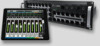
DL32R Front Panel - used
 |
View all Mackie DL32R manuals
Add to My Manuals
Save this manual to your list of manuals |
Page 5 highlights
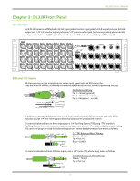
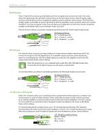
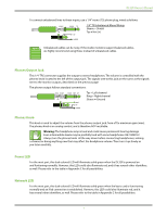
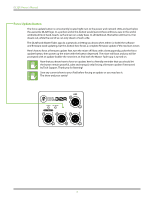
DL32R Owner's Manual Chapter 2 : DL32R Front Panel Introduction Each DL32R mixer is outfitted with 24 XLR input jacks, 8 combo input jacks, 14 XLR output jacks, an XLR AES output jack, 1/4" L/R monitor output jacks, one 1/4" phones output jack (and corresponding phones knob) and power and network LEDs. Let's take a look at each of these features, starting with the inputs. XLR and 1/4" Inputs All channels may accept a balanced mic or line-level signal using an XLR connector. They are wired as follows, according to standards specified by the AES (Audio Engineering Society). SHIELD 2 HOT COLD 3 1 1 3 2 SHIELD COLD HOT XLR Balanced Wiring: Pin 1 = Shield (ground) Pin 2 = Positive (+ or hot) Pin 3 = Negative (- or cold) In addition to accepting balanced mic or line-level signals using an XLR connector, channels 25-32 may also accept 1/4" line-level signals driven by balanced or unbalanced sources. To connect balanced lines to these inputs, use a 1/4" Tip-Ring-Sleeve (TRS) plug. "TRS" stands for Tip-Ring-Sleeve, the three connection points available on a stereo 1/4" or balanced phone jack or plug. TRS jacks and plugs are used for balanced signals and stereo headphones and are wired as follows: RING SLEEVE SLEEVE RING TIP TIP RING TIP SLEEVE 1/4" TRS Balanced Mono Wiring: Sleeve = Shield Tip = Hot (+) Ring = Cold (-) To connect unbalanced lines to these inputs, use a 1/4" mono (TS) phone plug, wired as follows: SLEEVE TIP SLEEVE TIP TIP 1/4" TS Unbalanced Mono Wiring: Sleeve = Shield Tip = Hot (+) SLEEVE 5
-
 1
1 -
 2
2 -
 3
3 -
 4
4 -
 5
5 -
 6
6 -
 7
7 -
 8
8 -
 9
9 -
 10
10 -
 11
11 -
12
-
13
-
14
-
15
-
16
-
17
-
18
-
19
-
20
-
21
-
22
-
23
-
24
-
25
-
26
-
27
-
28
-
29
-
30
-
31
-
32
-
33
-
34
-
35
-
36
 |
 |
