Mackie DL32R Owners Manual - Page 7
Phones Output Jack, Phones Knob, Power LED, Network LED - support
 |
View all Mackie DL32R manuals
Add to My Manuals
Save this manual to your list of manuals |
Page 7 highlights
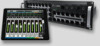
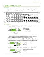
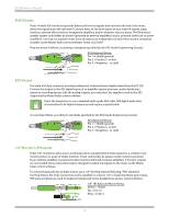
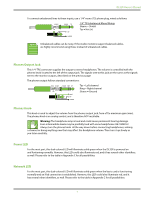
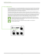
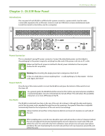
DL32R Owner's Manual To connect unbalanced lines to these inputs, use a 1/4" mono (TS) phone plug, wired as follows: SLEEVE TIP SLEEVE TIP TIP 1/4" TS Unbalanced Mono Wiring: Sleeve = Shield Tip = Hot (+) SLEEVE Unbalanced cables can be noisy. If the studio monitors support balanced cables, we highly recommend using those instead of unbalanced cables. Phones Output Jack This 1/4" TRS connector supplies the output to stereo headphones. The volume is controlled with the phones knob located to the left of the output jack. The signals sent to this jack are the same as the signals sent to the monitor outputs, described on the previous page. The phones output follows standard conventions: RING SLEEVE SLEEVE RING TIP TIP RING TIP SLEEVE Tip = Left channel Ring = Right channel Sleeve = Ground Phones Knob This knob is used to adjust the volume from the phones output jack, from off to maximum gain (max). The phones knob is an analog control, and is therefore NOT recallable. Warning: The headphone amp is loud and could cause permanent hearing damage. Even intermediate levels may be painfully loud with some headphones. BE CAREFUL! Always turn the phones knob all the way down before connecting headphones, soloing a channel or doing anything new that may affect the headphone volume. Then turn it up slowly as you listen carefully. Power LED For the most part, this dual-colored LED will illuminate solid green when the DL32R is powered on and funtioning normally. However, this LED could also illuminate red, and it has several other identifiers, as well. Please refer to the table in Appendix C for all possibilities. Network LED For the most part, this dual-colored LED will illuminate solid green when the basic card is functioning normally and an iPad connection is established. However, this LED could also illuminate red, and it has several other identifiers, as well. Please refer to the table in Appendix C for all possibilities. 7
-
 1
1 -
 2
2 -
 3
3 -
 4
4 -
 5
5 -
 6
6 -
 7
7 -
 8
8 -
 9
9 -
 10
10 -
 11
11 -
 12
12 -
13
-
14
-
15
-
16
-
17
-
18
-
19
-
20
-
21
-
22
-
23
-
24
-
25
-
26
-
27
-
28
-
29
-
30
-
31
-
32
-
33
-
34
-
35
-
36
 |
 |
