Makita EK7301 Owners Manual - Page 27
Cutting attachment in, central / side position, Repositioning the cutting attachment
 |
View all Makita EK7301 manuals
Add to My Manuals
Save this manual to your list of manuals |
Page 27 highlights
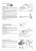
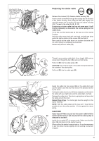
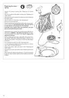
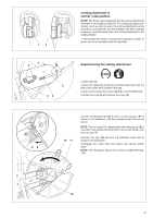
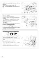
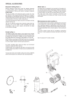
89 Cutting attachment in central / side position NOTE: The Power Cut is delivered with the cutting attachment mounted in the middle position (1). For cutting up against obstacles, such as curbs or walls, the cutting attachment can be mounted to one side (2). Use this position only when actually necessary, and afterwards return the cutting attachment to the middle position In this position the Power Cut has better balance, is easier to guide, and is not as fatiguing for the operator. Repositioning the cutting attachment Loosen nuts (5). Loosen the tightening screw (3) (counter-clockwise) until the end of the screw (4) is visible in the gap. Loosen and unscrew the screw (detail X, only for DPC8132). Unscrew the nuts (5) and remove the cover (6). 10 11 Use the combination tool (8) to lever out the stop pin (9) as shown in the illustration, until the protective hood (11) can be turned. NOTE: The turn stop (7) is deactivated when the stop pin (8) is removed. This permits the hood (11) to be turned farther than the turn stop (7). Unscrew the grip (10) and turn the protective hood (11) as shown in the illustration. Disengage the V-belt (12) and remove the cutting attachment. NOTE: The illustration shows the V-belt for models EK7300, 7301. 12 27
-
 1
1 -
2
-
3
-
4
-
5
-
6
-
7
-
8
-
9
-
10
-
11
-
12
-
13
-
14
-
15
-
16
-
17
-
18
-
19
-
20
-
21
-
 22
22 -
 23
23 -
 24
24 -
 25
25 -
 26
26 -
 27
27 -
 28
28 -
 29
29 -
 30
30 -
 31
31 -
 32
32 -
33
-
34
-
35
-
36
-
37
-
38
-
39
-
40
-
41
-
42
-
43
-
44
-
45
-
46
-
47
-
48
-
49
-
50
-
51
-
52
-
53
-
54
-
55
-
56
-
57
-
58
-
59
-
60
-
61
-
62
-
63
-
64
-
65
-
66
-
67
-
68
 |
 |
