Makita RT0700C Owners Manual - Page 11
Adjusting the depth of cut when using the plunge, base optional accessory - plunge base
 |
View all Makita RT0700C manuals
Add to My Manuals
Save this manual to your list of manuals |
Page 11 highlights
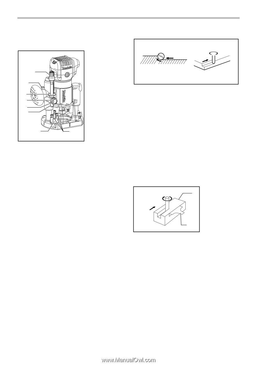
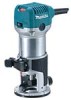
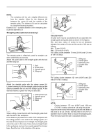
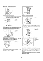
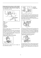
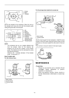
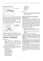
Adjusting the depth of cut when using the plunge base (optional accessory) 1 2 3 4 5 6 1. Adjusting knob 2. Lock lever 3. Depth pointer 4. Stopper pole setting nut 5. Fast-feed button 6. Stopper pole 7. Stopper block 8. Adjusting bolt 7 8 011983 Place the tool on a flat surface. Loosen the lock lever and lower the tool body until the bit just touches the flat surface. Tighten the lock lever to lock the tool body. Turn the stopper pole setting nut counterclockwise. Lower the stopper pole until it makes contact with the adjusting bolt. Align the depth pointer with the "0" graduation. The depth of cut is indicated on the scale by the depth pointer. While pressing the fast-feed button, raise the stopper pole until the desired depth of cut is obtained. Minute depth adjustments can be obtained by turning the adjusting knob (1 mm per turn). By turning the stopper pole setting nut clockwise, you can fasten the stopper pole firmly. Now, your predetermined depth of cut can be obtained by loosening the lock lever and then lowering the tool body until the stopper pole makes contact with the adjusting hex bolt of the stopper block. Always firmly hold the tool by both grip during operation. Set the tool base on the workpiece to be cut without the bit making any contact. Then turn the tool on and wait until the bit attains full speed. Lower the tool body and move the tool forward over the workpiece surface, keeping the tool base flush and advancing smoothly until the cutting is complete. When doing edge cutting, the workpiece surface should be on the left side of the bit in the feed direction. 1 4 2 3 2 4 1. Workpiece 2. Bit revolving direction 3. View from the top of the tool 4. Feed direction 001984 NOTE: • Moving the tool forward too fast may cause a poor quality of cut, or damage to the bit or motor. Moving the tool forward too slowly may burn and mar the cut. The proper feed rate will depend on the bit size, the kind of workpiece and depth of cut. Before beginning the cut on the actual workpiece, it is advisable to make a sample cut on a piece of scrap lumber. This will show exactly how the cut will look as well as enable you to check dimensions. • When using the straight guide, be sure to install it on the right side in the feed direction. This will help to keep it flush with the side of the workpiece. 2 1 1. Feed direction 3 2. Bit revolving direction 3. Workpiece 4. Straight guide 4 001985 11
-
 1
1 -
2
-
3
-
4
-
5
-
 6
6 -
 7
7 -
 8
8 -
 9
9 -
 10
10 -
 11
11 -
 12
12 -
 13
13 -
 14
14 -
 15
15 -
 16
16 -
17
-
18
-
19
-
20
-
21
-
22
-
23
-
24
-
25
-
26
-
27
-
28
-
29
-
30
-
31
-
32
-
33
-
34
-
35
-
36
-
37
-
38
-
39
-
40
-
41
-
42
-
43
-
44
-
45
-
46
-
47
-
48
 |
 |