Makita RT0700C Owners Manual - Page 4
Save These Instructions., Symbols, Functional Description - manual
 |
View all Makita RT0700C manuals
Add to My Manuals
Save this manual to your list of manuals |
Page 4 highlights
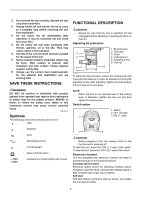
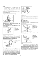
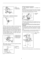
12. Do not leave the tool running. Operate the tool only when hand-held. 13. Always switch off and wait for the bit to come to a complete stop before removing the tool from workpiece. 14. Do not touch the bit immediately after operation; it may be extremely hot and could burn your skin. 15. Do not smear the tool base carelessly with thinner, gasoline, oil or the like. They may cause cracks in the tool base. 16. Use bits of the correct shank diameter suitable for the speed of the tool. 17. Some material contains chemicals which may be toxic. Take caution to prevent dust inhalation and skin contact. Follow material supplier safety data. 18. Always use the correct dust mask/respirator for the material and application you are working with. SAVE THESE INSTRUCTIONS. WARNING: DO NOT let comfort or familiarity with product (gained from repeated use) replace strict adherence to safety rules for the subject product. MISUSE or failure to follow the safety rules stated in this instruction manual may cause serious personal injury. USD201-2 Symbols The followings show the symbols used for tool. ・ volts ・ amperes ・ hertz ・ alternating current ・ no load speed ・ Class II Construction ・ revolutions or reciprocation per minute FUNCTIONAL DESCRIPTION CAUTION: • Always be sure that the tool is switched off and unplugged before adjusting or checking function on the tool. Adjusting bit protrusion 1 1. Bit protrusion 2 2. Tool base 3. Scale 3 4. Locking lever 5. Adjusting screw 6. Hex nut 4 5 6 011834 To adjust the bit protrusion, loosen the locking lever and move the tool base up or down as desired by turning the adjusting screw. After adjusting, tighten the locking lever firmly to secure the tool base. NOTE: • When the tool is not secured even if the locking lever is tightened, tighten the hex nut and then tighten the locking lever. Switch action 1. Switch 2. OFF (O) side 1 3. ON ( I ) side 2 3 011836 CAUTION: • Before plugging in the tool, always check to see that the tool is switched off. To start the tool, press the "ON ( I )" side of the switch. To stop the tool, press the "OFF (O)" side of the switch. Electronic function The tool equipped with electronic function are easy to operate because of the following features. Constant speed control Electronic speed control for obtaining constant speed. Possible to get fine finish, because the rotating speed is kept constant even under load condition. Soft start Soft-start feature minimizes start-up shock, and makes the tool start smoothly. 4
-
 1
1 -
 2
2 -
 3
3 -
 4
4 -
 5
5 -
 6
6 -
 7
7 -
 8
8 -
 9
9 -
 10
10 -
11
-
12
-
13
-
14
-
15
-
16
-
17
-
18
-
19
-
20
-
21
-
22
-
23
-
24
-
25
-
26
-
27
-
28
-
29
-
30
-
31
-
32
-
33
-
34
-
35
-
36
-
37
-
38
-
39
-
40
-
41
-
42
-
43
-
44
-
45
-
46
-
47
-
48
 |
 |
