Marantz VP8000 VP8000 User Manual - English - Page 5
Connector panel and Rear - projector
 |
View all Marantz VP8000 manuals
Add to My Manuals
Save this manual to your list of manuals |
Page 5 highlights
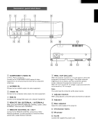
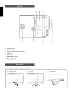
ENGLISH Connector panel and Rear mv z x , TRIG.OUT RGB IN EXTERNAL INTERNAL OUT IN REMOTE SW REMOTE CONTROL Y PB/CB PR/CR S-VIDEO IN COMPONENT VIDEO IN VIDEO IN bn c . ⁄2 INTRODUCTION ⁄1 . ⁄3 ⁄0 ⁄1 . z COMPONENT VIDEO IN Y, PB/CB, PR/CR connectors. Connect to the COMPONENT VIDEO output of video equipment or an A/V processor/receiver with a component video loop. x S-VIDEO IN Connect to the S-VIDEO output of a video equipment. c VIDEO IN Connect to the composite video output of a video equipment. v RGB IN Connect to the analog RGB output of a computer equipment. b REMOTE SW. (EXTERNAL / INTERNAL) When using the MARANTZ REMOTE CONTROL system, select EXTERNAL. Otherwise select INTERNAL. n REMOTE CONTROL IN / OUT Connect to the REMOTE CONTROL connectors of other Marantz equipment. It is then possible to control the whole system with a single Remote Controller. m TRIG. OUT (DC jack) When the projector is turned on, a 12 volt signal is sent to the equipment connected to the trigger. This allows automatic triggering of an accessory, such as a powered up/down screen, whenever the projector is turned on or off. When the unit is turned off, no voltage is output and when the unit is turned on, 12 V is output. Note You cannot use the connector as the power source. , Adjuster button When using adjuster, press the button and loosen an adjuster. . Adjuster ⁄0 Rear adjuster Adjust the vertical angle of the projector. ⁄1 Ventilation holes ⁄2 IR sensor ⁄3 AC IN Connect the supplied AC power cord. 4
-
 1
1 -
 2
2 -
 3
3 -
 4
4 -
 5
5 -
 6
6 -
 7
7 -
 8
8 -
 9
9 -
 10
10 -
 11
11 -
12
-
13
-
14
-
15
-
16
-
17
-
18
-
19
-
20
-
21
-
22
 |
 |
