Maytag MMMF8030PZ Owners Manual
Maytag MMMF8030PZ Manual
 |
View all Maytag MMMF8030PZ manuals
Add to My Manuals
Save this manual to your list of manuals |
Maytag MMMF8030PZ manual content summary:
- Maytag MMMF8030PZ | Owners Manual - Page 1
É DU FOUR À MICRO-ONDES 26 Sécurité du four à micro-ondes 26 Guide de connexion Internet pour les appareils connectés uniquement 28 Mise en garde FCC 29 ENTRETIEN ET RÉPARATION DU FOUR À MICROONDES 30 Nettoyage général 30 INSTRUCTIONS D'INSTALLATION 32 SPÉCIFICATIONS 32 Outils et Pièces 32 - Maytag MMMF8030PZ | Owners Manual - Page 2
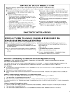
this manual. � This appliance must be grounded. Connect only to properly grounded outlet. See "GROUNDING INSTRUCTIONS" found or dropped. � This appliance should be serviced only by qualified service personnel. Contact nearest authorized service facility for examination, repair, or adjustment. - Maytag MMMF8030PZ | Owners Manual - Page 3
app. You will be guided through the steps to set up a user account and to connect your appliance. You Will Need: � A home wireless router supporting Wi-Fi, 2.4 Ghz with WPA2 security. If you are unsure of your router's capabilities, refer to the router manufacturer's instructions. � The router to be - Maytag MMMF8030PZ | Owners Manual - Page 4
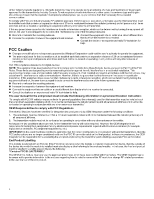
receiver is connected. � Consult the dealer or an experienced radio/TV technician for help. The user manual for the end product must include the following information in a prominent location Instruction: "To comply with FCC RF radiation exposure limits for general population, the antenna(s) used for - Maytag MMMF8030PZ | Owners Manual - Page 5
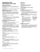
are off and the microwave oven is cool. Always follow label instructions on cleaning products. Soap, water, and a soft cloth or cooking, the oven bottom glass becomes very hot A. Embedded (see "Online control guide" for more Heating Plate details). Clean the glass after the "Oven too hot" - Maytag MMMF8030PZ | Owners Manual - Page 6
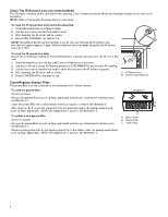
top. Clean it when the display shows the cleaning reminder or manual clean if necessary. NOTE: Wait until the product becomes idle and cools down . To clean the IR sensor lens when reminder appearing: 1. Follow the instructions on display to clean. A 2. Use the lens cleaner and lint-free swab - Maytag MMMF8030PZ | Owners Manual - Page 7
, but the filter alert will still appear every 6 months. You can follow the above steps to remove the alert. INSTALLATION INSTRUCTIONS REQUIREMENTS Tools and Parts Tools Needed � Measuring tape � Pencil � Scissors � Masking tape or thumbtacks � Drill � No. 2 Phillips screwdriver � Stud finder - Maytag MMMF8030PZ | Owners Manual - Page 8
Parts Supplied Part Screw Pack Drawing Damper Spacer 8 Description Qty Where can find? 3/16-24 x 3" round-head 2 bolts 1/4-20 x 3" flat-head bolts A 2 A. Inner Form in the cavity Washers 2 3/16" toggle nuts 2 1/4" x 2" lag screws 2 #6 x 3/8" Sheet metal 2 screws Power supply cord - Maytag MMMF8030PZ | Owners Manual - Page 9
"Online Ordering Information" section of the Quick Start Guide. Location Requirements Product Dimensions Check the opening where the and minimum 3/8" (1 cm) thickness drywall or plaster/lath within cabinet opening. � Support for weight of 150 lbs (68 kg) which includes microwave oven and items - Maytag MMMF8030PZ | Owners Manual - Page 10
the "Online Ordering Information" section of the Quick Start Guide. For cabinets with other dimension's, we suggest selecting other Whirlpool use an adapter. Do not use an extension cord. Failure to follow these instructions can result in death, fire, or electrical shock. Observe all governing codes - Maytag MMMF8030PZ | Owners Manual - Page 11
the plug provided with the appliance: if it will not fit the outlet, have a proper outlet installed by a qualified electrician. SAVE THESE INSTRUCTIONS This device complies with Industry Canada ICES-001. Prepare Microwave Oven Hood Combination WARNING Excessive Weight Hazard Use two or more people - Maytag MMMF8030PZ | Owners Manual - Page 12
can be done. A. End holes (on mounting plate) B. Cabinet opening vertical centerline C. Wall stud centerlines D. Holes for lag screws E. Support tabs F. Mounting plate center markers Wall Stud at End Holes Figure 3 B D A A,D E C F A. End holes (on mounting plate) B. Cabinet opening vertical - Maytag MMMF8030PZ | Owners Manual - Page 13
Find the Flush Point This product is designed to be flush with the cabinet, and the flush point should be found before installation. Don't install with the front of the microwave oven located behind the front of the cabinet/door. Flush to Cabinet door Flush to Cabinet door Don't install with the - Maytag MMMF8030PZ | Owners Manual - Page 14
C B A A. Back Edge of Cardboard Plate and Back Edge of Upper Cabinet B. Upper Cabinet Centerline and Center Marks on Cardboard Plate Flush to cabinet door E A B A D C A. Front Edge of Cardboard Plate and Upper Cabinet Door B. Upper Cabinet and Cardboard Plate 0.75" (1.9 cm) Line C. Mounting - Maytag MMMF8030PZ | Owners Manual - Page 15
Mark Rear Wall The microwave oven must be installed on a minimum of 1 wall stud, preferably 2, using a minimum of 1 lag screw, preferably 2. See "Find the Wall Stud(s)" section for find the wall studs. 1. Use a pencil to mark the power cord hole and two mounting nut holes. A 3. Hold the cardboard - Maytag MMMF8030PZ | Owners Manual - Page 16
6. Draw A and B two small circles, H and J is not necessary, depending on your need. Drill holes in Rear Wall 1. The mounting plate is located inside the outer foam in the cavity, take it out. A and B holes Drill holes in Upper Cabinet 1. Using a drill and the 0.75" (1.9 cm) hole saw, cut out the - Maytag MMMF8030PZ | Owners Manual - Page 17
and B hole, do not drill A and B hole, and follow the below instruction. In addition to being installed on at least 1 wall stud, the mounting plate on at least 1 wall stud as well as at both ends. 1. With the support tabs of the mounting plate facing forward, insert 3/16-24 x 3" round-head bolts - Maytag MMMF8030PZ | Owners Manual - Page 18
Stud at One End Hole (Figure 3 in Find the Wall Stud(s) section) 1. With the support tabs of the mounting plate facing forward, insert a 3/16-24 x 3" round-head bolt before install the microwave oven. And follow the propriated instruction to rotate the blower motor. If for recirculation installation - Maytag MMMF8030PZ | Owners Manual - Page 19
4. Disconnect the blower motor wire from the connector. A B 8. Lower blower motor back into the microwave oven. Exhaust ports face the back of the microwave oven. A A. Blower motor wire B. Connector 5. Lift blower motor out of microwave oven, and set aside. A A. Exhaust Port 9. Reconnect the - Maytag MMMF8030PZ | Owners Manual - Page 20
Plug into a grounded 3 prong outlet. Do not remove ground prong. Do not use an adapter. Do not use an extension cord. Failure to follow these instructions can result in death, fire, or electrical shock. 14. Plug in the microwave oven. Check if the vent fan runs with abnormal sounds, go back - Maytag MMMF8030PZ | Owners Manual - Page 21
7. Return the damper plate to its original horizontal position. A Install Damper Assembly for Roof Venting Installation 1. Check that damper blade moves freely and opens fully. 2. Insert damper assembly through the cabinet cutout so that the long tab of the damper assembly slides under the raised - Maytag MMMF8030PZ | Owners Manual - Page 22
3. Using 2 or more people, lift microwave oven and hang it on support tabs at the bottom of mounting plate. NOTE: To avoid damage to the thread in properly. Then tighten with tools. A B A. Mounting plate B. Support tabs 4. With front of microwave oven still tilted, thread power supply cord through - Maytag MMMF8030PZ | Owners Manual - Page 23
not tripped. Replace the fuse or reset the circuit breaker. If the problem continues, call an electrician. � Check that the power supply cord is plugged into a grounded 3 prong outlet. � See the User Instructions for troubleshooting information. 8. If for roof venting and wall venting, uninstall the - Maytag MMMF8030PZ | Owners Manual - Page 24
VENTING DESIGN SPECIFICATIONS This section is intended for architectural designer and builder/contractor reference only. NOTES: � Vent materials needed for installation are not provided with microwave hood combination. � We do not recommend using a flexible metal vent. � To avoid possible product - Maytag MMMF8030PZ | Owners Manual - Page 25
31/4" x 10" (8.3 x 25.4 cm) vent system = 73 ft (22.2 m) total A B D E C A. One 31/4" x 10" (8.3 x 25.4 cm) 90° elbow= 25 ft (7.6 m) B. 1 wall cap = 40 ft (12.2 m) C. 2 ft (0.6 m) + 6 ft (1.8 m) straight = 8 ft (2.4 m) D. 6 ft (1.8 m) E. 2 ft (0.6 m) 6" (152 mm) vent system = 73 ft (22.2 m) - Maytag MMMF8030PZ | Owners Manual - Page 26
effectuer une intervention d'entretien sur cet appareil. Communiquer avec l'entreprise de service autorisé la plus près de chez vous pour la vérification, fabriquées à la maison à l'aide d'une imprimante 3D). � Voir les instructions de nettoyage de la surface de la porte dans la » section « Entretien - Maytag MMMF8030PZ | Owners Manual - Page 27
� Ne pas couvrir les grilles ou toute partie du four avec du papier aluminium. Ceci entraînera la surchauffe du four. CONSERVER CES INSTRUCTIONS PRÉCAUTIONS POUR ÉVITER TOUTE EXPOSITION ÉVENTUELLE AU RAYONNEMENT EXCESSIF DE MICROONDES ET UTILISER L'APPAREIL SANS DANGER (a) Ne pas tenter de faire - Maytag MMMF8030PZ | Owners Manual - Page 28
l'appareil avant de l'utiliser. Bien lire et suivre le guide d'installation qui accompagne l'appareil. La connectabilité nécessite un avec sécurité WPA2. Pour vérifier les capacités du routeur, consulter le manuel d'instructions du fabricant du routeur. � Le routeur devra être en marche et connecté - Maytag MMMF8030PZ | Owners Manual - Page 29
et, s'il n'est pas installé ni utilisé conformément aux instructions, peut causer des interférences nuisibles aux communications radio. Cependant, il un technicien radio/télévision qualifié pour obtenir de l'aide. Le guide d'utilisation du produit doit comprendre les renseignements suivants : « Pour - Maytag MMMF8030PZ | Owners Manual - Page 30
et que le four à micro-ondes est froid. Toujours suivre les instructions figurant sur les étiquettes des produits de nettoyage. L'usage de savon ément) : Voir la section « Information de commande en ligne » du Guide de démarrage rapide pour commander. REVÊTEMENT INTÉRIEUR ANTIADHÉSIF (sur certains - Maytag MMMF8030PZ | Owners Manual - Page 31
: Attendre que le produit devienne inactif et refroidisse. Pour nettoyer la lentille du capteur IR lorsque le rappel apparaît : 1. Suivre les instructions affichées pour nettoyer. A 2. Utiliser le nettoyant pour lentilles et un coton-tige non pelucheux pour nettoyer. 3. Après le nettoyage, la - Maytag MMMF8030PZ | Owners Manual - Page 32
. Suivre les étapes ci-dessus pour supprimer l'alerte. Illustration 3 A B A. Trous B. Crochets C D C. Filtre au charbon D. Plaque inférieure INSTRUCTIONS D'INSTALLATION SPÉCIFICATIONS Outils et Pièces Outils nécessaires � Ruban à mesurer � Crayon � Ciseaux � Ruban-cache ou punaises � Perceuse - Maytag MMMF8030PZ | Owners Manual - Page 33
Pièces fournies Pièce Ensemble de vis Dessin Clapet Cale Description Vis à tête ronde de 3/16 -24 x 3 po Qté Où puis-je trouver? 2 Vis à tête plate de 1/4 - 20 x 3 po A 2 A. Mousse interne de la cavité Rondelles 2 Écrou à bascule de 3/16 2 po Tirefonds de 1/4 po x 2 po 2 Vis à tôle no - Maytag MMMF8030PZ | Owners Manual - Page 34
section « Information de commande en ligne » du Guide de démarrage rapide. Exigences d'emplacement Inspecter l'ouverture cm), et parement de plâtre/support d'enduit ou panneau de gypse d'épaisseur 3/8 po (1 cm) ou plus, dans l'ouverture de l'armoire. � Capacité de support de charge de 150 lb (68 - Maytag MMMF8030PZ | Owners Manual - Page 35
de profondeur B. Armoire C. Support de montage de bourrelet Pour commander, voir la section « Information de commande en ligne » du Guide de démarrage rapide. Pour Ne pas utiliser de rallonge. Le non-respect de ces instructions peut causer un décès, un incendie ou une décharge électrique. Observer - Maytag MMMF8030PZ | Owners Manual - Page 36
avec cet appareil; si elle ne correspond pas à la prise de sortie, faire installer une prise appropriée par un électricien qualifié. CONSERVER CES INSTRUCTIONS Cet appareil est conforme à la norme ICES-001 d'Industrie Canada. Risque de poids excessif Utiliser deux personnes ou plus pour déplacer et - Maytag MMMF8030PZ | Owners Manual - Page 37
l'axe central vertical (voir la section « Tracé sur le mur arrière »), seule une installation sans décharge à D. Trous pour tirefonds E. Pattes de support l'extérieur recyclage ou une installation avec décharge par le toit peut être réalisée. F. Marquage du centre sur plaque de montage A. Trous - Maytag MMMF8030PZ | Owners Manual - Page 38
la plaque de montage) B. Axe vertical central de l'ouverture dans l'armoire C. Axe vertical de montant de cloison D. Trous pour tirefonds E. Pattes de support F. Marquage du centre sur plaque de montage Trouver le point d'afleurement Ce produit est conçu pour être en affleurement avec l'armoire et - Maytag MMMF8030PZ | Owners Manual - Page 39
Maque pour l'armoire supérieure 1. Utiliser un ruban à mesurer pour mesurer et marquer clairement la position de l'axe central vertical de l'ouverture. S'assurer qu'elle s'aligne avec l'axe central vertical au mur. A B A. Axe central de l'armoire supérieure B. Axe central au mur REMARQUE : La - Maytag MMMF8030PZ | Owners Manual - Page 40
4. Utiliser un crayon pour marquer le trou du cordon d'alimentation et les deux trous des écrous de montage. B Marquer au crayon le trou d'évacuation sur le mur (pour installation avec décharge murale seulement). Sauter cette étape si l'appareil effectue la recirculation de l'air ou si l'évacuation - Maytag MMMF8030PZ | Owners Manual - Page 41
4. Trouver et tracer les deux lignes de position (A) du bas sur la plaque en carton. A Percer les trous dans l'armoire supérieure 1. Découper le trou (A) pour cordon d'alimentation à l'aide d'une perceuse et d'une scie-cloche de 0,75 po (1,9 cm). 2. Percer deux trous pour écrou de montage (B) de - Maytag MMMF8030PZ | Owners Manual - Page 42
B; si les montants de cloison ne se trouvent pas au niveau des trous A et B, ne pas percer des trous aux points A et B et suivre les instructions cidessous. En plus d'être fixé sur au moins un montant de cloison, on doit également fixer la plaque de montage sur le mur au niveau - Maytag MMMF8030PZ | Owners Manual - Page 43
plaque de montage doit être fixée sur le mur à aumoins un montant de cloison, ainsi qu'aux deux extrémités. 1. Alors que les pattes de support de la plaque de montage sont orientées vers l'avant, insérer des vis à tête ronde de 3/16-24 x 3 po dans les deux trous d'extr - Maytag MMMF8030PZ | Owners Manual - Page 44
avant d'installer le four à micro-ondes. Suivre les instructions appropriées pour réorienter le moteur du ventilateur. Pour plus tard. 2. Tourner et maintenir la plaque de support du clapet à la verticale, comme illustré. A A. Plaque de support du clapet 3. Retirer 2 vis de ventilateur fixant le - Maytag MMMF8030PZ | Owners Manual - Page 45
5. Sortir le moteur du four à micro-ondes et le garder pour plus tard. 8. Abaisser le moteur de ventilateur pour le réinsérer dans le four à micro-ondes. L'orifice de sortie fait face vers l'arrière du four à micro-ondes. A A A. Moteur de ventilateur 6. Utiliser une pince coupante pour découper - Maytag MMMF8030PZ | Owners Manual - Page 46
B. Trous de vis du moteur de ventilateur 12. Remettre la plaque de support du clapet à sa position horizontale d'origine. A Risque de décharge é utiliser d'adaptateur. Ne pas utiliser de rallonge. Le non-respect de ces instructions peut causer un décès, un incendie ou une décharge électrique. 14. - Maytag MMMF8030PZ | Owners Manual - Page 47
fixées dans les trous de vis du moteur de ventilateur pour que le moteur ne puisse pas bouger. 7. Remettre la plaque de support du clapet à sa position horizontale d'origine. A Installation du clapet antiretour Si l'installation s'effectue avec une recirculation, le clapet antiretour n'est pas - Maytag MMMF8030PZ | Owners Manual - Page 48
déplacer et installer l'appareil. Le non-respect de cette instruction peut causer une blessure au dos ou d'autres blessures. IMPORTANT immobilisée par du ruban adhésif. A B A. Plaque de montage B. Pattes de support 4. Alors que l'avant du four à micro-ondes est encore incliné, enfiler le cordon - Maytag MMMF8030PZ | Owners Manual - Page 49
ée à la terre. Ne pas enlever la prise de liaison à la terre. Ne pas utiliser d'adaptateur. Ne pas utiliser de rallonge. Le non-respect de ces instructions peut causer un décès, un incendie ou une décharge électrique. 3. Brancher le four à micro-ondes sur une prise à trois alvéoles reliée à la terre - Maytag MMMF8030PZ | Owners Manual - Page 50
les doigts C. Filtre à graisse D. Ressort A. Trous B. Crochets C. Filtre au charbon D. Plaque inférieure L'installation est maintenant terminée. Conserver les instructions d'installation pour une éventuelle réutilisation future. A Minimum 12 1/8 po (30,8 cm) Recommandations 18 1/8 po (46 cm - Maytag MMMF8030PZ | Owners Manual - Page 51
Dans le cas de la décharge à travers le toit, si on doit utiliser un raccord de transition (de rectangulaire à rond), veiller à disposer d'un espace libre d'au moins 3 po (7,6 cm) entre le sommet du four à micro-ondes et le raccord de transition. Voir l'illustration « Raccord de transition - Maytag MMMF8030PZ | Owners Manual - Page 52
Conduit d'un diamètre de 6 po (152 mm) = longueur totale 73 pi (22,2 m) A B E F C D A. Deux coudes 90° = 20 pi (6,1 m) B. 1 bouche de décharge murale = 40 pi (12,2 m) C. 1 raccord de transition de conduit rectangulaire/conduit rond = 5 pi (1,5 m) D. Sections de conduit rectiligne 2 pi (0,6 m) - Maytag MMMF8030PZ | Owners Manual - Page 53
NOTES - Maytag MMMF8030PZ | Owners Manual - Page 54
NOTES - Maytag MMMF8030PZ | Owners Manual - Page 55
NOTES - Maytag MMMF8030PZ | Owners Manual - Page 56
NOTES
-
 1
1 -
 2
2 -
 3
3 -
 4
4 -
 5
5 -
 6
6 -
 7
7 -
8
-
9
-
10
-
11
-
12
-
13
-
14
-
15
-
16
-
17
-
18
-
19
-
20
-
21
-
22
-
23
-
24
-
25
-
26
-
27
-
28
-
29
-
30
-
31
-
32
-
33
-
34
-
35
-
36
-
37
-
38
-
39
-
40
-
41
-
42
-
43
-
44
-
45
-
46
-
47
-
48
-
49
-
50
-
51
-
52
-
53
-
54
-
55
-
56
 |
 |

IMPORTANT:
Save for local electrical inspector's use.
IMPORTANT :
À conserver pour consultation par l'inspecteur local des installations électriques.
MICROWAVE OVEN HOOD COMBINATION
OWNER’S MANUAL
MANUEL DE L’UTILISATEUR DE L’ENSEMBLE FOUR À
MICRO-ONDES/HOTTE
Table of Contents/Table des matières
MICROWAVE OVEN SAFETY
.............................................
2
Microwave Oven Safety
..................................................
2
Internet Connectivity Guide for Connected Appliances Only
....
3
FCC Caution
.................................................................
4
MICROWAVE OVEN MAINTENANCE AND CARE
..................
5
General Cleaning
...........................................................
5
INSTALLATION INSTRUCTIONS
........................................
7
REQUIREMENTS
.............................................................
7
Tools and Parts
.............................................................
7
Location Requirements
...................................................
9
Product Dimensions
.......................................................
9
Installation Dimensions
.................................................
10
Electrical Requirements
................................................
10
INSTALLATION
.............................................................
11
Prepare Microwave Oven Hood Combination
.....................
11
Installation Types
.........................................................
11
Find the Cardboard Plate
...............................................
12
Find the Wall Stud(s)
....................................................
12
Find the Flush Point
......................................................
13
Mark Upper Cabinet
.....................................................
13
Mark Rear Wall
............................................................
15
Drill holes in Upper Cabinet
............................................
16
Drill holes in Rear Wall
..................................................
16
Attach Mounting Plate to Wall
.........................................
17
Rotate Blower Motor
.....................................................
18
Install Damper Assembly
...............................................
21
Install the Microwave Oven
............................................
22
Complete Installation
....................................................
23
VENTING DESIGN SPECIFICATIONS
................................
24
SÉCURITÉ DU FOUR À MICRO-ONDES
............................
26
Sécurité du four à micro-ondes
.......................................
26
Guide de connexion Internet pour les appareils connectés
uniquement
................................................................
28
Mise en garde FCC
......................................................
29
ENTRETIEN ET RÉPARATION DU FOUR À MICRO-
ONDES
........................................................................
30
Nettoyage général
........................................................
30
INSTRUCTIONS D’INSTALLATION
...................................
32
SPÉCIFICATIONS
..........................................................
32
Outils et Pièces
...........................................................
32
Exigences d’emplacement
.............................................
34
Dimensions du produit
..................................................
34
Dimensions d’installation
...............................................
35
Spécifications électriques
..............................................
35
INSTALLATION
.............................................................
36
Préparation de l’ensemble four à micro-ondes/hotte
............
36
Type d’installation
........................................................
36
Trouver la plaque de carton
............................................
37
Trouver les montants de cloison
......................................
37
Trouver le point d’afleurement
........................................
38
Maque pour l’armoire supérieure
.....................................
39
Marque sur le mur arrière
..............................................
40
Percer les trous dans l’armoire supérieure
.........................
41
Perçage de trous dans le mur arrière
................................
42
Fixation de la plaque de montage au mur
..........................
43
Réorientation du moteur du ventilateur
.............................
44
Installation du clapet antiretour
.......................................
47
Installation du four à micro-ondes
....................................
48
Achever l’installation
.....................................................
49
SPÉCIFICATION DE LA CONCEPTION DU CIRCUIT
D’ÉVACUATION
.............................................................
50
W11688933A