Meade 12 inch Instruction Manual - Page 26
SUPERWEDGE For 10 and 12LX200, Mounting the Telescope On the Wedge
 |
View all Meade 12 inch manuals
Add to My Manuals
Save this manual to your list of manuals |
Page 26 highlights
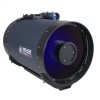
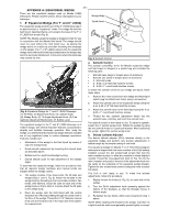
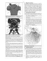
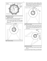
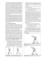
- 26 - the tilt-plate. If the main crossbar of the DLA is already c. tightened into place this will inhibit your installation of the tilt- plate. You will therefore see that by releasing the screws on the ends of the DLA crossbar your installation of the wedge tilt- plate will be facilitated. 2. SUPERWEDGE (For 10" and 12"LX200) The Superwedge permits use of the 10" and 12" LX200 d. telescope in an astronomical, or "equatorial," mode. The wedge fits onto the field tripod, described below, and accepts the base of the 10" and 12" LX200 fork mount (Fig. 10). NOTE: The Meade Superwedge is designed solely for use in e. conjunction with the Meade field tripod. The Superwedge should never be used without the field tripod (e.g., by placing the Superwedge alone on a table top and then mounting the telescope on the wedge). The 10" and 12" LX200, placed onto the Superwedge alone without the field tripod attached to the wedge may become seriously imbalanced, to the point where the telescope may actually tip over. Holding the threaded rod in position, place the Superwedge on top of the tripod head so that the threaded stud extending from the tripod head passes through the center hole on the wedge floor. Make sure the pin extending from the bottom of the azimuth thrust bar is positioned in the slot on the tangent arm (see Fig. 11a., above). Install the large hand knob/compass onto the threaded stud. Pass the three 5\16-18 X 1-1/4" button head screws through the clearance slots on the wedge floor and thread them into the tripod head. The lower tilt plate locking screws (3, Fig. 11) are installed in the factory to allow the tilt plate to be adjusted for any latitude greater than 25 degrees and less than 55 degrees. If viewing in a region with a latitude greater than 55 degrees, move the locking bolts to the lower mounting holes (4, Fig. 11). 1 2 5 3 4 4 Meade 8 7 6 1 3 2 9 Fig. 10: Superwedge for 10" LX200 Telescope. (1) Tilt Plate; (2) Attachment Screw; (3) Latitude Scale; (4) Wedge Body; (5) Tilt Angle Adjustment Screw; (6) Vernier Pointer; (7) Bubble Level; (8) Fine Latitude Control Knob; (9) Azimuth Control Knob. The Superwedge for the 10" and 12" LX200 telescope is of modern design, with several important features incorporated to simplify and facilitate telescope operation. After using the Superwedge for your telescope, you will find that the functional design features included are of very significant value in routine telescope operations. Some of these features include: • Attachment of the Superwedge to the field tripod by means of only one manual knob. (For photographic applications with the telescope where extreme steadiness is required, 3 additional hex-head screws are provided). • Quick azimuth adjustment by loosening the manual knob as described above. • Bubble level for rapid tripod/wedge leveling. • Etched latitude scale for fast adjustment of the latitude angle. • Built-in latitude adjustment control. To assemble the Superwedge, follow this procedure (note that all required wedge hardware and manual knobs are shipped within the wedge carton): a. Locate the two 8-32 nylon set screws on the rim of the tripod head and remove them. Attach the tangent arm to the tripod using the supplied 8-32 X 1/2" socket cap screws. (See Fig. 11a., below.) b. Push the field tripod threaded rod up so that the threaded rod extends above the top of the tripod head. Fig. 11: Mounting Superwedge. (1) Azimuth Thrust Bar Pin; (2) Tangent Arm; (3) Lower Tilt Plate Locking Screws; (4) Lower Mounting Holes. 3. Mounting the Telescope On the Wedge With 7" or 8" LX200 telescopes, three knobs are supplied for mounting the telescope's drive base to the tilt-plate of the equatorial wedge. With the 10" and 12" LX200, three socket screws are provided for this purpose. 1 2 3 4 5 Fig. 12: Mounting to the Equatorial Wedge. (1) Drive Base Attachment Knob; (2) Telescope Drive Base; (3) Slot for Attachment Knob; (4) Additional Attachment Knob Holes; (5) Attachment Knob/Compass.
-
 1
1 -
2
-
3
-
4
-
5
-
6
-
7
-
8
-
9
-
10
-
11
-
12
-
13
-
14
-
15
-
16
-
17
-
18
-
19
-
20
-
 21
21 -
 22
22 -
 23
23 -
 24
24 -
 25
25 -
 26
26 -
 27
27 -
 28
28 -
 29
29 -
 30
30 -
 31
31 -
32
-
33
-
34
-
35
-
36
-
37
-
38
-
39
-
40
-
41
-
42
-
43
-
44
-
45
-
46
-
47
-
48
-
49
-
50
-
51
-
52
-
53
-
54
-
55
-
56
-
57
-
58
-
59
-
60
-
61
-
62
-
63
-
64
 |
 |
