Meade 12 inch Instruction Manual - Page 7
TELESCOPE ASSEMBLY, The Field Tripod - in feet
 |
View all Meade 12 inch manuals
Add to My Manuals
Save this manual to your list of manuals |
Page 7 highlights
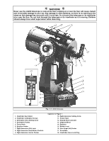
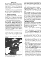
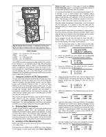
-7- TELESCOPE ASSEMBLY Alternately, the field tripod can be used in conjunction with the Use the following steps to assemble your telescope. appropriate optional equatorial wedge (APPENDIX A, page 25) NOTE: If the section is not applicable to all LX200 models, it is noted at the beginning of each section. for long exposure astrophotography. The equatorial wedge permits alignment of the telescope's Polar Axis with the Celestial Pole (or North Star). 1. The Field Tripod The field tripods (Figs. 2 and 3) for Meade 8", 10", and 12" LX200 telescopes are supplied as completely assembled units, except for the spreader bar (4, Fig. 2) and the 6 lock knobs (2 knobs for each of the 3 tripod legs) used to adjust the height of the tripod. These knobs are packed separately for safety in shipment. For visual (i.e., non-photographic) observations, the drive base (17, Fig. 1) of the telescope's fork mount is attached directly to the field tripod. The telescope in this way is mounted in an "Altazimuth" ("Altitude-Azimuth," or "vertical-horizontal") format. The telescope in this configuration moves along vertical and horizontal axes, corresponding respectively to the Declination and Right Ascension axes (explained later in this manual) in an astronomical observing mode. After removing the field tripod from its shipping carton, stand the tripod vertically, with the tripod feet down and with the tripod still fully collapsed (see Fig. 3). Grasp two of the tripod legs and, with the full weight of the tripod on the third leg, gently pull the legs apart to a fully open position. Thread in the 6 lock-knobs (2 on each tripod leg) near the foot of each tripod leg (Fig. 2). These lock-knobs are used to fix the height of the inner, extendible tripod leg sections. NOTE: "Firm feel" tightening is sufficient; over-tightening may result in stripping of the knob threads or damage to the tripod legs and results in no additional strength. The spreader bar (4, Fig. 2) has been removed for shipment. To replace, first remove the threaded rod (2, Fig.2) from the tripod head (1, Fig. 2); a small piece of plastic holds the threaded rod in place. Remove the small plastic bag that is 1 stapled to the threaded rod. This bag contains the "C" clip 2 retainer (used below) and an extra clip. Slide the spreader bar onto the threaded rod (note the correct orientation as shown in Fig. 2) and position the threaded rod back through the tripod head. Place the clip retainer ( a "C" clip) into the slot in the threaded rod. This clip holds the threaded rod in place. See Fig. 3. 4 3 5 Position the spreader bar so that the 3 arms of the spreader bar are lined up with the 3 tripod legs. Place the entire telescope onto the top of the tripod head, and thread the threaded rod into the central threaded hole in the bottom of the drive base of the telescope. Tighten the tension knob (3, Fig. 2); firm tightening of the tension knob is sufficient to result in rigid positioning of the tripod legs. 7 6 To vary the tripod height, loosen the 6 lock-knobs, slide the 3 inner tripod leg sections out to the desired height, and firmly retighten (but do not overtighten) the 6 lock-knobs. To collapse the tripod (after removing the telescope and equatorial wedge, if applicable) for storage follow these steps: Fig. 2: LX200 Field Tripod. (1) Tripod Head; (2) Threaded Rod; (3) Tension Knob; (4) Spreader Bar; (5) Lock Knobs; (6) Extension Strut; (7) Tension Hub. "C" Clip • Rotate the spreader bar 60° from its assembled position, so that one spreader bar arm is located between each adjacent pair of tripod legs. • At the base of the tripod is a 3-vane extension strut system, with a circular hub at its center (7, Fig. 2). Grasp the tripod head (1, Fig. 2) with one hand and, with the other hand, pull directly "up" on the central hub of the extension strut system. This operation will cause the tripod legs to move inward to a collapsed position. PRECAUTIONARY NOTES • If the tripod does not seem to extend or collapse easily, do not force the tripod legs in or out. By following the instructions above, the tripod will function properly, but if you are unclear on the proper procedure, forcing the tripod into an incorrect position may damage the extension strut system. • Do not overtighten the 6 lock-knobs used to fix the inner tripod leg sections at various heights. "Firm feel" tightening is sufficient. • Be sure the spreader bar (4, Fig. 2) is not upside-down on the threaded rod. Fig. 3: Field Tripod (collapsed).
-
 1
1 -
 2
2 -
 3
3 -
 4
4 -
 5
5 -
 6
6 -
 7
7 -
 8
8 -
 9
9 -
 10
10 -
 11
11 -
 12
12 -
13
-
14
-
15
-
16
-
17
-
18
-
19
-
20
-
21
-
22
-
23
-
24
-
25
-
26
-
27
-
28
-
29
-
30
-
31
-
32
-
33
-
34
-
35
-
36
-
37
-
38
-
39
-
40
-
41
-
42
-
43
-
44
-
45
-
46
-
47
-
48
-
49
-
50
-
51
-
52
-
53
-
54
-
55
-
56
-
57
-
58
-
59
-
60
-
61
-
62
-
63
-
64
 |
 |
