Meade 12 inch Instruction Manual - Page 52
Collimation of the Optical System
 |
View all Meade 12 inch manuals
Add to My Manuals
Save this manual to your list of manuals |
Page 52 highlights
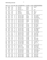
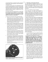
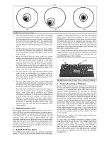
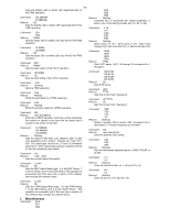
- 52 - environmental pollutants, or temperature changes reacting with 2. Collimation of the Optical System the interior paint, causing outgassing or water condensation, or combinations thereof. The optical collimation (alignment) of any astronomical telescope used for serious purposes is important, but in cases It is possible to clean the interior of the optical system yourself of the Schmidt-Cassegrain design of the 8", 10", and 12" or to have it done professionally. In the case of the former, take LX200, such collimation is absolutely essential for good great care in handling the optics. Any impact or rough handling performance. Take special care to read and understand this can damage the surfaces, which may require complete optical section well so that your LX200 will give you the best optical replacement at Meade Instruments at substantial cost. Meade performance. Instruments assumes no liability for damage incurred to the telescope by the customer. The cleaning techniques described above are used while cleaning the interior of the optical system, with one exception: Do not apply cleaning solutions to the front surface mirrored optics. Only use the soft camel hair brush and the suggested ear syringe for removing particles. The corrector plate can be cleaned in the normal manner. NOTE: The 7" LX200 does not require collimation. For final optical tests, every Meade Schmidt-Cassegrain is precisely collimated at the factory before shipment. Our company is well aware that through shipment and normal handling, the optical alignment can be degraded. The design of the optical support system make the method of collimation easy to do. Even the uninitiated can make an alignment of the optics to the same high precision that is performed at the Meade To remove the corrector plate, follow the instructions below: Instruments Optical Laboratories. a. Remove the six (8" and 12" models) or the eight (10" model) stainless steel screws that hold the corrector plate retaining ring with the raised white lettering in place. This should be done with the Drive Base placed flat on a work bench, and the optical tube assembly pointed up at a 45degree angle with the declination lock secure to prevent accidental dislodging of the corrector plate. b. Remove the plastic retaining ring and locate the two white alignment marks, one at the edge of the corrector plate lens and one beside it on the black metal front cell. These two marks line up and serve as the precise rotational position of the corrector plate in the optical train. If no marks exist, make them yourself with a small paintbrush and some white paint, so that when you return the corrector plate to the front cell you are putting it back in the same position that you took it off. c. Remove the corrector plate from the telescope, holding it by the plastic central secondary housing. Gently flip it over so that the secondary mirror is facing you, then reinsert the corrector plate back into the front cell. This will allow you full access to clean the interior optical surfaces without touching them with your fingers. d. When cleaning is complete, replace the corrector plate in it's original position, carefully lining up the rotational index marks described in paragraph b, above. Then replace the retainer. Partially thread in all of the stainless steel screws, then, one at a time, snug the screws down to prevent the corrector plate from rotating in the front cell. Take care not to overtighten the screws as it will stress the corrector plate lens. e. A final check of the optical system is to inspect for proper collimation (alignment) of the optics. To check the collimation of your LX200, center a bright star that is overhead, or use a reflected "hot spot" of reflected sunlight from a chrome car bumper or a telephone pole insulator, with the supplied 26mm eyepiece. To make a correct evaluation of the alignment it helps if the telescope has been allowed to either cool down or warm up to the ambient temperature where the instrument is set up. Temperature differences between the optics and the outside air can cause distortion in the images. With the star or hot spot centered, de-focus the image. You will notice that the out of focus star image looks like a ring of light (the dark center of the ring is the shadow of the secondary mirror). Turn the focus knob until the ring of light fills about 1/8th of the eyepiece field. Take note that if you keep de-focusing the star past about 1/8th of a field, that the ring will look perfectly concentric (even on all sides) even if the optics are out of alignment, thus preventing you from seeing any misalignments. If the ring of light does not seem to be even on all sides, or if the dark center seems to be offset in the in the ring of light, follow the method below: a. To make collimation easy, the only adjustments possible on the 8", 10", and 12" LX200 come from the three set screws (1, 2, and 3, Fig.26) located at the edge of the outer surface of the secondary mirror housing. WARNING: DO NOT FORCE THE 3 COLLIMATION SCREWS PAST THEIR NORMAL TRAVEL AND DO NOT LOOSEN THEM MORE THAN 2 FULL TURNS (COUNTER-CLOCKWISE DIRECTION), OR THE SECONDARY MIRROR MAY COME LOOSE FROM ITS SUPPORT. YOU WILL FIND THAT THE ADJUSTMENTS ARE VERY SENSITIVE: USUALLY, ONLY TURNING A COLLIMATION SCREW 1/2 A TURN WILL GIVE DRAMATIC RESULTS. 1 2 3 Fig. 26: Collimation of the Optical System. (1), (2), (3) Set screws for adjusting collimation. b. While looking at the de-focused star image and noticing which direction the darker shadow is offset in the ring of light or noticing which part of the ring is the thinnest (1, Fig. 27), place your index finger in front of the telescope so that it touches one of the collimation set screws. You will see the shadow of your finger in the ring of light. Move your finger (or an assistants finger) around the edge of the black plastic secondary mirror support until you see the shadow of the finger crossing the thinnest part of the ring of light. At this point, look at the front of the telescope where your (or your assistants) finger is aiming. It will either be pointing directly at a set screw, or it will be between two set screws aiming at the set screw on the far side of the black plastic secondary mirror support. This is the set screw that you will adjust. c. Using the telescope's slow motion controls, move the defocused image to the edge of the eyepiece field of view (2, Fig. 27), in the same direction as the darker shadow is offset in the ring of light.
-
 1
1 -
2
-
3
-
4
-
5
-
6
-
7
-
8
-
9
-
10
-
11
-
12
-
13
-
14
-
15
-
16
-
17
-
18
-
19
-
20
-
21
-
22
-
23
-
24
-
25
-
26
-
27
-
28
-
29
-
30
-
31
-
32
-
33
-
34
-
35
-
36
-
37
-
38
-
39
-
40
-
41
-
42
-
43
-
44
-
45
-
46
-
 47
47 -
 48
48 -
 49
49 -
 50
50 -
 51
51 -
 52
52 -
 53
53 -
 54
54 -
 55
55 -
 56
56 -
 57
57 -
58
-
59
-
60
-
61
-
62
-
63
-
64
 |
 |