Meade 12 inch Instruction Manual - Page 54
Meade 12 inch Manual
 |
View all Meade 12 inch manuals
Add to My Manuals
Save this manual to your list of manuals |
Page 54 highlights
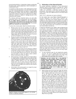
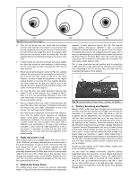
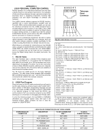
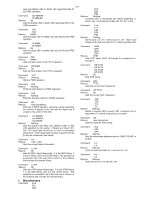
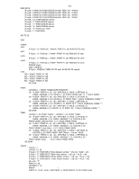
APPENDIX F: - 54 - LX200 PERSONAL COMPUTER CONTROL Remote operation of a computerized telescope has only been a fanciful dream for most amateur astronomers. The realization of fully controlling a telescope through a personal computer has previously been a staggering proposition involving high monetary cost and expert knowledge of software and hardware. 6 3 52 4 1 Telescope Panel Connector The LX200's internal software supports the RS-232 interface, requiring only a serial communication program such as Procomm. With a serial communication program, you can use the individual commands from the LX200 Command Set to simulate keypad control functions of the LX200. Every LX200 command and mode is available to explore the Object Library, to adjust slewing speeds, or to adjust focus with the optional #1206 Electric Focuser, just to name a few, with a simple RS232 line connection to virtually any computer. If you are not a professional programmer, but wish to explore remote operation of the LX200 with your computer, there are after-market software programs available specifically for the LX200, including AstroSearch from Meade Instruments Corp. What follows is a schematic for constructing your own RS-232 cable, a program to test the RS-232 communication line called LX200 TEST, the LX200 Command Set, and LX200 DEMO, which is a program that you can enter into your computer to access the Object Library, slew to the object, and center the image. 1. RS-232 Cable The input hardware uses a standard 6-line telephone jack connector, pre-attached to a 6-conductor flat line telephone style cable (of any length, up to 100' and perhaps even more, depending on the gauge of the cable). You will also need either a 9-pin or 25-pin RS-232 connector, whichever your computer uses for the serial port. All of the above items are available at most electronics hardware stores. Fig. 29 shows the LX200 pinouts for the 6-line telephone connector. The table below shows standard IBM compatible DB-9 and DB-25 serial port pin outs,** and how they should be connected to the LX200 6-line modular connector. NOTE: Only 3 wires are required. 2. LX200 Test Program Once you have the RS-232 cable constructed you will want to test the cable. Below is a simple program called "LX200 TEST" that is written in GW Basic programming language and will work with virtually any IBM compatible computer. LX200 TEST is an effective program to fully check the RS-232 line communications from your personal computer to the LX200, allowing you to concentrate on de-bugging your RS-232 cable. 63 5 24 1 Fig. 29: LX200 Modular Connector. 10 CLS 20 DEFINT A-X 30 OPEN "COM1:9600,N,8,1,CD0,CS0,DS0,RS," FOR RANDOM AS #1 50 key1$ = INKEY$: IF key1$ = "" THEN GO TO 50 60 REM KEY1S 70 IF key1$ = CHR$(119) THEN GOSUB 200: REM "w" key 80 IF key1$ = CHR$(101) THEN GOSUB 200: REM "e" key 90 IF key1$ = CHR$(110) THEN GOSUB 200: REM "n" key 100 IF key1$ = CHR$(115) THEN GOSUB 200: REM "s" key 105 IF key1$ = "x" THEN END: REM To exit test. 110 GO TO 50 120 END 200 REM directions 210 REM west 220 IF key1$ = "w" THEN a$ = "#:Mw#": PRINT #1, a$: REM GO west 230 REM east 240 IF key1$ = "e" THEN a$ = "#:Me#": PRINT #1, a$: REM GO east 250 REM north 260 IF key1$ = "n" THEN a$ = "#:Mn#": PRINT #1, a$: REM GO north 270 REM south: 280 IF key1$ = "s" THEN a$ = "#:Ms#": PRINT #1, a$: REM GO south 290 key1$ = INKEY$: 300 IF key1$ = CHR$(32) THEN GO TO 400 ELSE GO TO 200 400 REM This stops motion (by hitting SPACE bar). 410 B$ = "#:Qe#": PRINT #1, B$ 420 B$ = "#:Qw#": PRINT #1, B$ 430 B$ = "#:Qn#": PRINT #1, B$ 440 B$ = "#:Qs#": PRINT #1, B$ 450 RETURN 460 END To enter the following program, first load BASIC or GWBASIC (whichever your computer system uses), then type in the following program. When complete, be sure to save the program as "LX200TST.BAS." To use the above program, connect the completed cable to your PC serial port and to the LX200 RS-232 Port. Load BASIC (or GWBASIC), if not already loaded, and run "LX200TST.BAS." Nothing will appear on the computer screen. Press any one of the N, S, E, or W (lower case) keys on your 6 WIRE MODULAR CONNECTOR #1 #2 #3 #4 #5 #6 LX200 RS-232 CONNECTOR PIN OUT CODE LEGEND DESCRIPTION TO DB-9 CONNECTOR PIN#*** +12 VOLTS DC NOT USED MISC. SERIAL OUT NOT USED PC TRANSMIT DATA #3 GROUND #5 PC RECEIVE DATA #2 MISC. SERIAL IN NOT USED TO DB-25 CONNECTOR PIN#*** NOT USED NOT USED #2 #7 #3 NOT USED
-
 1
1 -
2
-
3
-
4
-
5
-
6
-
7
-
8
-
9
-
10
-
11
-
12
-
13
-
14
-
15
-
16
-
17
-
18
-
19
-
20
-
21
-
22
-
23
-
24
-
25
-
26
-
27
-
28
-
29
-
30
-
31
-
32
-
33
-
34
-
35
-
36
-
37
-
38
-
39
-
40
-
41
-
42
-
43
-
44
-
45
-
46
-
47
-
48
-
 49
49 -
 50
50 -
 51
51 -
 52
52 -
 53
53 -
 54
54 -
 55
55 -
 56
56 -
 57
57 -
 58
58 -
 59
59 -
60
-
61
-
62
-
63
-
64
 |
 |
