Meade EclipseView 82mm Instruction Manual - Page 40
Collimation
 |
View all Meade EclipseView 82mm manuals
Add to My Manuals
Save this manual to your list of manuals |
Page 40 highlights
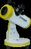
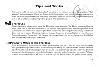
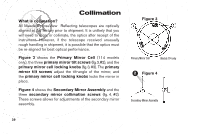
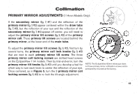
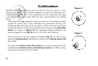
Collimation What is collimation? All Meade EclipseView Reflecting telescopes are optically aligned at the factory prior to shipment. It is unlikely that you will need to align, or collimate, the optics after receipt of the instrument. However, if the telescope received unusually rough handling in shipment, it is possible that the optics must be re-aligned for best optical performance. Figure 3 shows the Primary Mirror Cell (114 models only), the three primary mirror tilt screws (fig.3,#2), and the primary mirror cell locking knobs (fig. 3, #3). The primary mirror tilt screws adjust the tilt-angle of the mirror, and the primary mirror cell locking knobs locks the mirror in place. Figure 4 shows the Secondary Mirror Assembly and the three secondary mirror collimation screws (fig. 4, #2). These screws allows for adjustments of the secondary mirror assembly. 40 39 Figure 3 Primary Mirror Cell Models 114 only 2 Figure 4 Secondary Mirror Assembly
-
 1
1 -
2
-
3
-
4
-
5
-
6
-
7
-
8
-
9
-
10
-
11
-
12
-
13
-
14
-
15
-
16
-
17
-
18
-
19
-
20
-
21
-
22
-
23
-
24
-
25
-
26
-
27
-
28
-
29
-
30
-
31
-
32
-
33
-
34
-
 35
35 -
 36
36 -
 37
37 -
 38
38 -
 39
39 -
 40
40 -
 41
41 -
 42
42 -
 43
43 -
 44
44 -
 45
45 -
46
-
47
-
48
-
49
-
50
-
51
-
52
-
53
-
54
-
55
-
56
 |
 |