Meade EclipseView 82mm Instruction Manual - Page 41
Correct Collimation
 |
View all Meade EclipseView 82mm manuals
Add to My Manuals
Save this manual to your list of manuals |
Page 41 highlights
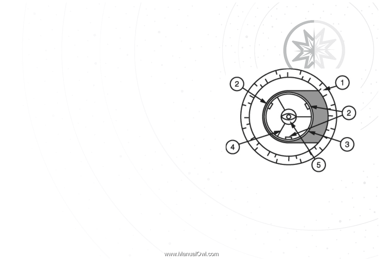
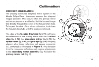
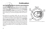
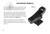
Collimation CORRECT COLLIMATION: The properly collimated (aligned) mirror system in the Meade EclipseView telescope assures the sharpest images possible. This occurs when the primary mirror and secondary mirror are tilted so that the focused image falls directly through the center of the focuser draw tube. To inspect the view of the mirror collimation, look down the focuser draw tube with the eyepiece removed. The edge of the focuser drawtube (fig. 5, #1), will frame the reflections of the primary mirror with the 3 mirror clips (fig. 5, #2), the secondary mirror (fig. 5, #3), the spider vanes (fig.5,#4), and your eye (fig.5,#5). Properly aligned, all of these reflections will appear concentric (i.e., centered) as illustrated in Figure 5. Any deviation from the concentric reflections will require adjustments to the secondary mirror assembly (fig. 4) and/or the primary mirror cell (fig. 3). Figure 5 41 40
-
 1
1 -
2
-
3
-
4
-
5
-
6
-
7
-
8
-
9
-
10
-
11
-
12
-
13
-
14
-
15
-
16
-
17
-
18
-
19
-
20
-
21
-
22
-
23
-
24
-
25
-
26
-
27
-
28
-
29
-
30
-
31
-
32
-
33
-
34
-
35
-
 36
36 -
 37
37 -
 38
38 -
 39
39 -
 40
40 -
 41
41 -
 42
42 -
 43
43 -
 44
44 -
 45
45 -
 46
46 -
47
-
48
-
49
-
50
-
51
-
52
-
53
-
54
-
55
-
56
 |
 |