Metabo RFEV 19-125 RT Operating Instructions - Page 13
Attaching the accessory, Maintenance, Cleaning
 |
View all Metabo RFEV 19-125 RT manuals
Add to My Manuals
Save this manual to your list of manuals |
Page 13 highlights
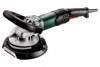
For optimal dust extraction, use the connecting sleeve 6.30796. We recommend using an antistatic suction hose with diameter 35 mm. 7. Attaching the accessory Disconnect the mains plug before changing any accessories. The machine must be switched off and the spindle must be at a standstill. 7.1 Locking the spindle Press in the spindle locking knob (9) only when the spindle is stationary! - Press in the spindle locking button (9) and turn the spindle (7) by hand until you feel the spindle locking button engage. ENGLISH en Switch on first, then guide the accessory towards the workpiece. The machine must not be allowed to draw in additional dust and shavings. When switching the machine on and off, keep it away from dust deposits. After switching off the machine, only place it down when the motor has come to a standstill. Avoid inadvertent starts: always switch the tool off when the plug is removed from the mains socket or if there has been a power cut. In continuous operation, the machine continues running if it is forced out of your hands. Therefore, always hold the machine with both hands using the handles provided, stand in a safe position and concentrate. Machines with the designation W...RT: Torque activation (with dead man's lever) 7.2 Fitting/removing the routing tool For safety reasons, use the safety guard (19) with the attached depth stop (22). See illustration B on page 2. To fit: - Lock the spindle (see chapter 7.1). - Screw on and tighten the routing tool (6) using the 2-hole spanner (5) in a clockwise direction. To remove: - Lock the spindle (see chapter 7.1). Unscrew the routing tool (6) with the 2-hole spanner (5) in an anticlockwise direction. 0 I 18 Switching on: Slide the trigger switch (18) forwards and then push the trigger switch (18) upwards. Switching off: Release the trigger switch (18). Machines with the designation W...RT: Continuous operation (depending on features) 7.3 Fitting/removing the diamond cup wheel For safety reasons, use the safety guard (19) with the attached depth stop (22). See illustration C on page 2. To fit: - Fit the support flange (12) on the spindle. (7) The flange should not turn on the spindle when properly attached. - Lay the diamond cup wheel (11) on the support flange (12) so that it lies flat along the support flange. - The 2 sides of the clamping nut (10) are different. Screw the clamping nut onto the spindle so that the band of the clamping nut (10) is facing upward. - Lock the spindle (see chapter 7.1). Turn the clamping nut (10) clockwise using the 2-hole spanner (5) to secure. To remove: - Lock the spindle (see chapter 7.1). Turn the clamping nut (10) anticlockwise using the 2-hole spanner (5) to unscrew. 8. Use 8.1 Setting speed Set the optimum speed on the setting wheel (18), depending on the application. I 18 Switching on: Switch the machine on as described above. Now slide the trigger switch (18) forwards again and release in the front position to lock the trigger switch (18) (continuous operation). Switching off: Push the trigger switch (18) upwards and release. 9. Maintenance Replace worn or damaged routing wheels (see figure, page 2): - Removing the routing tool (see chapter 7.2). - Extract the screw (13) in an anticlockwise direction. Remove the safety disc (14). - Replace all routing wheels as shown. (Always use the same type of routing wheels). -Reassemble all parts as shown. Insert and turn the screw (13) in a clockwise direction and tighten with 13 Nm ± 1 Nm. 10. Cleaning 0 8.2 Switching On and Off Always guide the machine with both hands. Motor cleaning: blow compressed air through the rear ventilation slots of the machine regularly, 13
-
 1
1 -
2
-
3
-
4
-
5
-
6
-
7
-
 8
8 -
 9
9 -
 10
10 -
 11
11 -
 12
12 -
 13
13 -
 14
14 -
 15
15 -
 16
16 -
 17
17 -
 18
18 -
19
-
20
-
21
-
22
-
23
-
24
-
25
-
26
-
27
-
28
-
29
-
30
-
31
-
32
-
33
-
34
-
35
-
36
-
37
-
38
-
39
-
40
-
41
-
42
-
43
-
44
-
45
-
46
-
47
-
48
-
49
-
50
-
51
-
52
-
53
-
54
-
55
-
56
-
57
-
58
-
59
-
60
-
61
-
62
-
63
-
64
-
65
-
66
-
67
-
68
-
69
-
70
-
71
-
72
-
73
-
74
-
75
-
76
-
77
-
78
-
79
-
80
-
81
-
82
-
83
-
84
-
85
-
86
-
87
-
88
-
89
-
90
-
91
-
92
 |
 |
