NEC PX-61XM2A 42VP4/42XM2/50XM3/61XM2 - Page 44
AUTO ID, Example: Setting ON, IMAGE ADJUST, Example: Adjusting the vertical position, DISP. MODE,
 |
View all NEC PX-61XM2A manuals
Add to My Manuals
Save this manual to your list of manuals |
Page 44 highlights
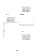
DISP. MODE Select the screen mode from between two options (Splitting, Blanking). Example: Setting "BLANK" Perform Steps 1-2 of VIDEO WALL, then... 3. Use the v and w buttons to select "DISP. MODE". 4. Use the ᮤ and ᮣ buttons to select "BLANK". The mode switches as follows each time the ᮤ or ᮣ button is pressed: SPLIT ↔ BLANK VIDEO WALL DIVIDER : 1 POSITION DISP. MODE : BLANK AUTO ID : OFF IMAGE ADJUST P. ON DELAY : OFF PLE LINK : OFF REPEAT TIMER : OFF SEL. ADJ. EXIT RETURN Information Ⅵ DISP. MODE settings SPLIT ......... Combines enlarged screens and creates multiple screens. BLANK ....... Corrects misalignment of combined screen portions and creates multiple screens AUTO ID This feature automatically sets the ID numbers of multiple displays connected to each other. Example: Setting "ON" Set the ID number for the No. 1 display on ID NUMBER menu. Perform Steps 1-2 of VIDEO WALL, then... 3. Use the v and w buttons to select "AUTO ID". 4. Use the ᮤ and ᮣ buttons to select "ON", then press the MENU/ENTER button. The mode switches as follows each time the ᮤ or ᮣ button is pressed: OFF ↔ ON AUTO ID 1 2 AUTO ID : ON 1 2 3 4 3 8 9 4 7 6 5 WIRED CABLE CONNECTION TURN ADJ. EXIT RETURN Information Ⅵ AUTO ID settings ON ...... Enables Auto ID function. In the case shown below, display 1 will be set as ID 1, display 2 as ID2, etc. REMOTE IN No.1 No.2 No.4 No.3 Display 1 REMOTE OUT REMOTE IN No.1 No.2 No.4 No.3 Display 2 REMOTE OUT REMOTE OUT No.1 No.2 No.4 No.3 Display 4 REMOTE OUT REMOTE IN No.1 No.2 No.4 No.3 REMOTE IN Display 3 OFF .... Disables Auto ID function. IMAGE ADJUST The position of the image can be adjusted and flickering of the image can be corrected. Example: Adjusting the vertical position Perform Steps 1-2 of VIDEO WALL, then... 3. Use the v and w buttons to select "IMAGE ADJUST", then press the MENU/ENTER button. The "IMAGE ADJUST" screen appears. 4. Use the v and w buttons to select "V-POSITION". IMAGE ADJUST ASPECT MODE : NORMAL V-POSITION H-POSITION V-HEIGHT H-WIDTH AUTO PICTURE : OFF FINE PICTURE PICTURE ADJ. SEL. ADJ. EXIT RETURN 5. Adust using the ᮤ and ᮣ buttons. V-POSITION * If neither the ᮤ or ᮣ button is pressed within 5 seconds, the current setting is set and the previous screen reappears. Information Ⅵ IMAGE ADJUST settings These are the same functions as the IMAGE ADJUST menu on page 22. 37
-
 1
1 -
2
-
3
-
4
-
5
-
6
-
7
-
8
-
9
-
10
-
11
-
12
-
13
-
14
-
15
-
16
-
17
-
18
-
19
-
20
-
21
-
22
-
23
-
24
-
25
-
26
-
27
-
28
-
29
-
30
-
31
-
32
-
33
-
34
-
35
-
36
-
37
-
38
-
 39
39 -
 40
40 -
 41
41 -
 42
42 -
 43
43 -
 44
44 -
 45
45 -
 46
46 -
 47
47 -
 48
48 -
 49
49 -
50
-
51
-
52
 |
 |
