Netgear DG834G DG834Gv5 Setup Manual - Page 6
Hardware Features, Front Panel - factory reset
 |
UPC - 606449029918
View all Netgear DG834G manuals
Add to My Manuals
Save this manual to your list of manuals |
Page 6 highlights
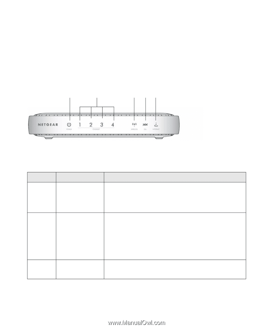
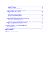
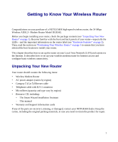
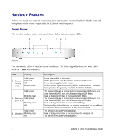
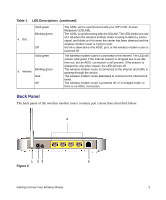
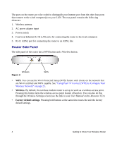
Hardware Features Before you install and connect your router, take a moment to become familiar with the front and back panels of the router-especially the LEDs on the front panel. Front Panel The wireless modem router front panel shown below contains status LEDs. 1 2 3 45 Figure 1 You can use the LEDs to verify various conditions. The following table describes each LED.. Table 1. LED Descriptions LED 1. Power, factory reset Activity Solid green Solid red Off Factory reset Solid green Blinking green 2. Ethernet Solid Amber ports 1-4 Blinking amber Off Solid green 3. Wireless Blinking green Off Description Power is supplied to the router. POST (Power-On Self-Test) failure or device malfunction. Power is not supplied to the router. During a reset, lights momentarily, blinks red three times, and then turns green as the gateway resets to the factory defaults. The powered device is connected to the associated Ethernet Local Area Network (LAN) port, which is operating at 100 Mbps. Data is being transmitted or received at 100 Mbps. The powered device is connected to the associated Ethernet Local Area Network (LAN) port, which is operating at 10 Mbps. Data is being transmitted or received at 10 Mbps. No link is detected on this port, or modem powered off, or no cable or no powered device is connected to the associated port. The Wireless Access Point is enabled. Data is being transmitted or received over the wireless link. The Wireless Access Point is disabled. 2 Getting to Know Your Wireless Router
-
 1
1 -
 2
2 -
 3
3 -
 4
4 -
 5
5 -
 6
6 -
 7
7 -
 8
8 -
 9
9 -
 10
10 -
 11
11 -
 12
12 -
13
-
14
-
15
-
16
-
17
-
18
-
19
-
20
-
21
-
22
-
23
-
24
-
25
-
26
-
27
-
28
-
29
-
30
-
31
-
32
-
33
-
34
-
35
-
36
-
37
-
38
-
39
-
40
-
41
-
42
-
43
-
44
 |
 |