Netgear DG834Nv1 Reference Manual - Page 76
IP Address, IP Subnet Mask, RIP Direction, Out Only, In Only, RIP Version
 |
View all Netgear DG834Nv1 manuals
Add to My Manuals
Save this manual to your list of manuals |
Page 76 highlights
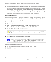
DG834N RangeMax NEXT Wireless ADSL2+ Modem Router Reference Manual These addresses are part of the Internet Engineering Task Force (IETF)-designated private address range for use in private networks, and should be suitable in most applications. If your network has a requirement to use a different IP addressing scheme, you can make those changes in this menu. Figure 6-2 The LAN TCP/IP Setup parameters are: • IP Address: This is the LAN IP address of the wireless modem router. • IP Subnet Mask: This is the LAN Subnet Mask of the wireless modem router. Combined with the IP address, the IP Subnet Mask allows a device to know which other addresses are local to it, and which must be reached through a gateway or wireless modem router. • RIP Direction: RIP (Router Information Protocol) allows a wireless modem router to exchange routing information with other routers. The RIP Direction selection controls how the Wireless Modem Router sends and receives RIP packets. Both is the default. - When set to Both or Out Only, the wireless modem router will broadcast its routing table periodically. - When set to Both or In Only, it will incorporate the RIP information that it receives. - When set to None, it will not send any RIP packets and will ignore any RIP packets received. • RIP Version: This controls the format and the broadcasting method of the RIP packets that the wireless modem router sends. It recognizes both formats when receiving. By default, this is set for RIP-1. - RIP-1 is universally supported. RIP-1 is probably adequate for most networks, unless you have an unusual network setup. 6-4 Advanced Configuration v1.0, May 2006
-
 1
1 -
2
-
3
-
4
-
5
-
6
-
7
-
8
-
9
-
10
-
11
-
12
-
13
-
14
-
15
-
16
-
17
-
18
-
19
-
20
-
21
-
22
-
23
-
24
-
25
-
26
-
27
-
28
-
29
-
30
-
31
-
32
-
33
-
34
-
35
-
36
-
37
-
38
-
39
-
40
-
41
-
42
-
43
-
44
-
45
-
46
-
47
-
48
-
49
-
50
-
51
-
52
-
53
-
54
-
55
-
56
-
57
-
58
-
59
-
60
-
61
-
62
-
63
-
64
-
65
-
66
-
67
-
68
-
69
-
70
-
 71
71 -
 72
72 -
 73
73 -
 74
74 -
 75
75 -
 76
76 -
 77
77 -
 78
78 -
 79
79 -
 80
80 -
 81
81 -
82
-
83
-
84
-
85
-
86
-
87
-
88
-
89
-
90
-
91
-
92
-
93
-
94
-
95
-
96
-
97
-
98
-
99
-
100
 |
 |
