Netgear DGN2200v1 DGN2200 Setup Manual - Page 8
Button, Description, Table 1., LED and Front Panel Button Descriptions, continued - router
 |
View all Netgear DGN2200v1 manuals
Add to My Manuals
Save this manual to your list of manuals |
Page 8 highlights
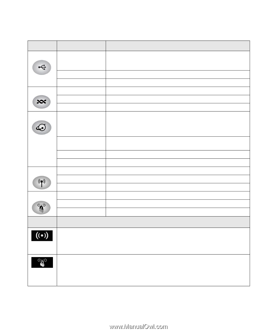
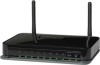
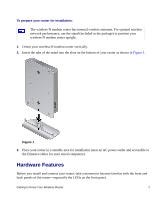
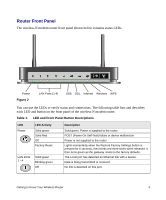
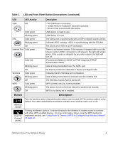
Table 1. LED and Front Panel Button Descriptions (continued) LED LED Activity Description USB Off Solid green Blinking green DSL Solid green Blinking green Off Internet Port Solid green Wireless WPS Solid red Blinking green Off Solid green Blinking green Off Solid green Blinking green Off • No USB device connected. • "Safely Remove Hardware" has been activated. • An error has occurred with the device. USB device is ready to use. USB device is in use. The ADSL port is synchronized with an ISP's network-access device. Indicates ADSL training-ADSL is synchronizing with the DSLAM. The unit is off or there is no IP connection. There is an Internet session. If the session is dropped due to an idle timeout, and an ADSL connection is still present, the light will remain green. If the session is dropped for any other reason, the light will turn off. IP connection failed (no DHCP or PPoE response, PPPoE authentication failed). Data is being transmitted over the ADSL port. No Internet connection detected or device in bridged mode. Indicates that the Wireless port is initialized. Data is being transmitted or received over the wireless link. The Wireless Access Point is turned off. WPS wireless security is being enabled. The device is in the 2-minute interval to synchronize security. WPS is not being set or enabled. Button Description Wireless On/Off Push 'N' Connect (WPS) Turn the wireless radio in the wireless-N modem router on and off. The wireless radio is on by default. The LED located below this button indicates if the wireless radio is on or off. Pushing this button opens a 2-minute window for the wireless-N modem router to connect with other WPS-enabled devices. For more information, about using the WPS method to implement security, see "Using Push 'N' Connect (WPS) to Configure Your Wireless Network" on page 22. Getting to Know Your Wireless Router 4
-
 1
1 -
2
-
 3
3 -
 4
4 -
 5
5 -
 6
6 -
 7
7 -
 8
8 -
 9
9 -
 10
10 -
 11
11 -
 12
12 -
 13
13 -
14
-
15
-
16
-
17
-
18
-
19
-
20
-
21
-
22
-
23
-
24
-
25
-
26
-
27
-
28
-
29
-
30
-
31
-
32
-
33
-
34
-
35
-
36
-
37
-
38
-
39
-
40
-
41
-
42
-
43
 |
 |