Netgear FS108P Configuring for Avaya IP Telephones - Page 18
Verification Steps for the FS726TP PoE, 4. Verification Steps for the FS726TP QoS - poe switch
 |
UPC - 606449037814
View all Netgear FS108P manuals
Add to My Manuals
Save this manual to your list of manuals |
Page 18 highlights
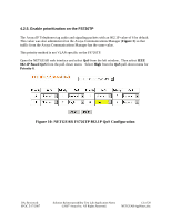
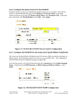
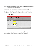
6.3. Verification Steps for the FS726TP PoE After power cycling the FS726TP, attach a PC to the PC port of one of the Avaya IP Telephones. Open a web browser with the IP address of the FS726TP. Select POE from the left hand menu and verify that all of the Avaya IP Telephones are being powered as expected (Figure 4). Select Port Configuration from the left window of the FS726TP Web page and verify that the speed and duplex of all the powered Avaya IP Telephone ports is 100Mbps/Full. Verify that the speed and duplex for Port 26 matches the configuration of the upstream router. 6.4. Verification Steps for the FS726TP QoS These steps require a traffic generation device. Open the FS726TP Administration Web Page. Select VLAN from the right hand menu. Select IEEE 802.1Q VLAN in the right hand window. From the pull down menu select VLAN 1 (Default). For the uplink port that is used to connect the FS726TP to the router select T (Tag egress packets) on VLAN 1. Select Apply. Configure the router to support VLAN 1 on the uplink from the FS726TP. Connect a Gigabit traffic source to Port 25 (on VLAN 1) of the FS726TP. Connect the second traffic source at another Ethernet switch that can be reached via the router connected to Port 26 of the FS726TP. Verify that the traffic sources can send IP addressed UDP packets to each other. Place a call from one of the Avaya IP Telephones to a PSTN line on Avaya Communications Manager. Select the Network Audio Quality display on the Avaya IP Telephone and record the audio statistics. Perform a throughput test between the two Gigabit traffic sources. While the throughput test is in progress, verify the audio quality of the call. The call should remain clear. On the Network Audio Quality display on the Avaya IP Telephone, note the audio statistics. Packet Loss should remain 0%. The delays may increase significantly depending on the performance of the entire LAN. The fact that Packet Loss remains 0% indicates that packets are being prioritized on the uplink to the router over the data in the throughput test. It is possible that Packet Loss occurs outside of the FS726TP. A Packet Loss higher that 0% is not strictly a proof that the FS726TP is incorrectly configured. A careful examination of the configuration screens should be done to verify that the FS726TP is correctly configured. JJA; Reviewed: SPOC 5/17/2007 Solution & Interoperability Test Lab Application Notes ©2007 Avaya Inc. All Rights Reserved. 18 of 20 NETGEARAppNotes.doc
-
 1
1 -
2
-
3
-
4
-
5
-
6
-
7
-
8
-
9
-
10
-
11
-
12
-
 13
13 -
 14
14 -
 15
15 -
 16
16 -
 17
17 -
 18
18 -
 19
19 -
 20
20
 |
 |