Netgear N300 User Manual - Page 6
Meet Your Extender, Front Panel - router
 |
View all Netgear N300 manuals
Add to My Manuals
Save this manual to your list of manuals |
Page 6 highlights
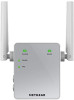
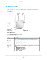
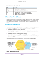
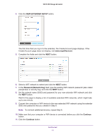
N300 WiF Range Extender Meet Your Extender Before you install your extender, familiarize yourself with its LEDs, buttons, and port. Front Panel Router Link LED Device Link LED Power LED WPS LED Power On/Off button WPS button Factory Reset button Figure 1. Front panel The following table describes the LEDs. Table 1. Front panel LEDs Ethernet port LED Router Link Device Link Description This LED indicates the connection between the extender and the router or access point: • Solid green. Best connection. • Solid amber. Good connection. • Solid red. Poor connection. • Off. No connection. This LED indicates the connection between the extender and a computer or WiFi device: • Solid green. Best connection. • Solid amber. Good connection. • Solid red. Poor connection. • Off. No connection. Overview 6
-
 1
1 -
 2
2 -
 3
3 -
 4
4 -
 5
5 -
 6
6 -
 7
7 -
 8
8 -
 9
9 -
 10
10 -
 11
11 -
 12
12 -
13
-
14
-
15
-
16
-
17
-
18
-
19
-
20
-
21
-
22
-
23
-
24
-
25
-
26
-
27
-
28
-
29
-
30
-
31
-
32
-
33
-
34
-
35
-
36
-
37
-
38
-
39
-
40
-
41
-
42
-
43
 |
 |
