Netgear WFS709TP WFS709TP Setup Manual - Page 43
Connect the WFS709TP Smart Wireless Switch to your computer., System name - access points
 |
UPC - 606449052336
View all Netgear WFS709TP manuals
Add to My Manuals
Save this manual to your list of manuals |
Page 43 highlights
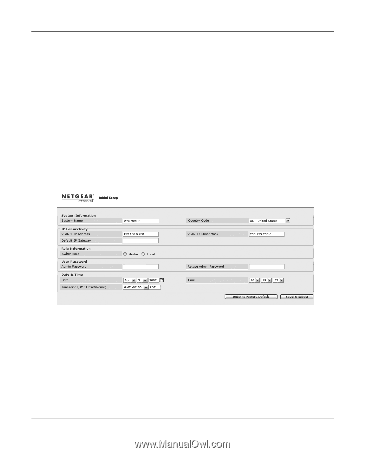
WFS709TP ProSafe Smart Wireless Switch Software Administration Manual To run the initial setup: 1. Connect the WFS709TP Smart Wireless Switch to your computer. a. Unpack the box and verify the contents. b. Prepare a PC with an Ethernet adapter. If this PC is already part of your network, record its TCP/IP configuration settings. Configure the PC with a static IP address of 192.168.0.200. c. Connect an Ethernet cable to the PC. d. Securely insert the other end of the cable into one of the Fast Ethernet Ports on the WFS709TP. e. Connect the power cord for the WFS709TP. f. Turn on your computer, open a web browser, and connect to http://192.168.0.250 (Figure 2-4). Figure 2-4 2. Enter the following information: • System name. A user-defined name for the switch (up to 64 characters). • VLAN 1 IP address & subnetwork mask-the IP address that the switch will use to communicate with other switches and with access points. • Default gateway. The default gateway on the switch's planned subnetwork (the default gateway and VLAN 1 IP address must be in the same network). • Role. Enter one of these roles for the switch: Deploying a Basic WFS709TP System 2-7 v1.0, June 2007
-
 1
1 -
2
-
3
-
4
-
5
-
6
-
7
-
8
-
9
-
10
-
11
-
12
-
13
-
14
-
15
-
16
-
17
-
18
-
19
-
20
-
21
-
22
-
23
-
24
-
25
-
26
-
27
-
28
-
29
-
30
-
31
-
32
-
33
-
34
-
35
-
36
-
37
-
 38
38 -
 39
39 -
 40
40 -
 41
41 -
 42
42 -
 43
43 -
 44
44 -
 45
45 -
 46
46 -
 47
47 -
 48
48 -
49
-
50
-
51
-
52
-
53
-
54
-
55
-
56
-
57
-
58
-
59
-
60
-
61
-
62
-
63
-
64
-
65
-
66
-
67
-
68
-
69
-
70
-
71
-
72
-
73
-
74
-
75
-
76
-
77
-
78
-
79
-
80
-
81
-
82
-
83
-
84
-
85
-
86
-
87
-
88
-
89
-
90
-
91
-
92
-
93
-
94
-
95
-
96
-
97
-
98
-
99
-
100
-
101
-
102
-
103
-
104
-
105
-
106
-
107
-
108
-
109
-
110
-
111
-
112
-
113
-
114
-
115
-
116
-
117
-
118
-
119
-
120
-
121
-
122
-
123
-
124
-
125
-
126
-
127
-
128
-
129
-
130
-
131
-
132
-
133
-
134
-
135
-
136
-
137
-
138
-
139
-
140
-
141
-
142
-
143
-
144
-
145
-
146
-
147
-
148
-
149
-
150
-
151
-
152
-
153
-
154
-
155
-
156
-
157
-
158
-
159
-
160
-
161
-
162
-
163
-
164
-
165
-
166
-
167
-
168
-
169
-
170
-
171
-
172
-
173
-
174
-
175
-
176
-
177
-
178
-
179
-
180
-
181
-
182
-
183
-
184
-
185
-
186
-
187
-
188
-
189
-
190
-
191
-
192
-
193
-
194
-
195
-
196
-
197
-
198
-
199
-
200
-
201
-
202
-
203
-
204
-
205
-
206
-
207
-
208
-
209
-
210
-
211
-
212
-
213
-
214
-
215
-
216
-
217
-
218
-
219
-
220
-
221
-
222
 |
 |