Netgear XSM7224S XSM7224S Hardware Installation Guide
Netgear XSM7224S - ProSafe 10 Gigabit Stackable Manual
 |
UPC - 606449073706
View all Netgear XSM7224S manuals
Add to My Manuals
Save this manual to your list of manuals |
Netgear XSM7224S manual content summary:
- Netgear XSM7224S | XSM7224S Hardware Installation Guide - Page 1
Managed Stackable Switch XSM7224S Hardware Installation Guide 350 East Plumeria Drive San Jose, CA 95134 USA November 2010 202-10751-01 v1.0 - Netgear XSM7224S | XSM7224S Hardware Installation Guide - Page 2
Managed Stackable Switch XSM7224S © 2010 NETGEAR, Inc.© 2010 by NETGEAR, Inc. All rights reserved. No [email protected] Website: http://www.netgear.com Phone: 1-888-NETGEAR, for US & Canada only. For other countries, see your Support information card. Trademarks NETGEAR, the NETGEAR logo, ProSafe - Netgear XSM7224S | XSM7224S Hardware Installation Guide - Page 3
Console to the Switch 16 Chapter 3 Troubleshooting Troubleshooting Chart 18 Additional Troubleshooting Suggestions 19 Appendix A Technical Specifications Specifications for XSM7224S 20 Specifications for GSM7328S and GSM7352S 23 Appendix B Default Configuration Settings Appendix C Notification - Netgear XSM7224S | XSM7224S Hardware Installation Guide - Page 4
Managed Stackable Switch XSM7224S 4 | Contents - Netgear XSM7224S | XSM7224S Hardware Installation Guide - Page 5
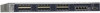
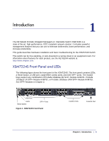
. This guide describes hardware installation and basic troubleshooting for the XSM7224S Switch This switch can be free-standing, or rack-mounted in a wiring closet or an equipment room. For information about features for each product, see the NETGEAR website at http://www.netgear.com. XSM7224S Front - Netgear XSM7224S | XSM7224S Hardware Installation Guide - Page 6
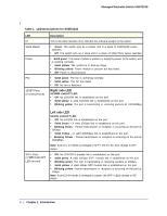
Managed Stackable Switch XSM7224S l Table 1. LED Descriptions for XSM7224S LED ID Stack Master Power Fan 10GBT Ports (2 LEDs per port) Description This is the stack member ID (1-99) that the software assigns to the switch. • Green: The switch acts as a master unit in a stack of XSM7224S series - Netgear XSM7224S | XSM7224S Hardware Installation Guide - Page 7
Managed Stackable Switch XSM7224S XSM7224S Rear Connector Power Supply Figure 2. XSM7224S Rear Panel Safety Instructions Use the following safety guidelines gets wet, see the appropriate section in your troubleshooting guide or contact your trained service provider. • Do not push any objects into - Netgear XSM7224S | XSM7224S Hardware Installation Guide - Page 8
Managed Stackable Switch XSM7224S • Use the product only with approved equipment. • Allow the most of North and South America and some Far Eastern countries such as South Korea and Taiwan - 100 V, 50 Hz in eastern Japan and 100 V, 60 Hz in western Japan - 230 V, 50 Hz in most of Europe, the Middle - Netgear XSM7224S | XSM7224S Hardware Installation Guide - Page 9
• Rack-mounting kit • Null-modem serial cable (RS-232) with 9-pin connectors • Resource CD: The CD either includes these documents or links to access them: - ProSafe 7200 Managed Switch CLI Manual, Version 9.0 - NETGEAR 7000 Series Managed Switch Administration Guide - NETGEAR Installation Guide for - Netgear XSM7224S | XSM7224S Hardware Installation Guide - Page 10
Managed Stackable Switch XSM7224S place it on a secure and clean surface. See "Select a Location" on page 2-10. 3. Remove all packing material. 4. Make sure The switch can be mounted in a standard 19-inch (48.26-centimeter) rack, wall-mounted, or left freestanding (placed on a tabletop). 10 | - Netgear XSM7224S | XSM7224S Hardware Installation Guide - Page 11
spaces on the bottom of the switch. The rubber footpads cushion the switch against shock and vibrations. Installing the Switch in a Rack To install the switch in a rack, you will need the 19-inch rack-mount kit supplied with your switch. 1. Attach the supplied mounting brackets to the side of the - Netgear XSM7224S | XSM7224S Hardware Installation Guide - Page 12
Managed Stackable Switch XSM7224S 2. Use the provided Phillips head screws to fasten the brackets to the sides of the switch. mounting bracket Figure 1. Installing the Switch in a Rack 3. Tighten the screws with a No. 1 Phillips screwdriver to secure each bracket. 4. Align the bracket and rack holes - Netgear XSM7224S | XSM7224S Hardware Installation Guide - Page 13
Managed Stackable Switch XSM7224S 1. Connect one end of the AC power adapter cable to the rear of the switch, and the other end to a grounded 3-pronged AC outlet. 2. Check the Power LED on the front panel of the switch. The LED should light up in the following sequence: • The LED turns yellow as the - Netgear XSM7224S | XSM7224S Hardware Installation Guide - Page 14
Managed Stackable Switch XSM7224S 2. Press firmly to ensure that the module seats into the connector. Figure 3. Insert the SFP+ or SPF Module into the Switch 14 | Chapter 2. Hardware Installation - Netgear XSM7224S | XSM7224S Hardware Installation Guide - Page 15
Managed Stackable Switch XSM7224S Creating a Stack You can connect up to four switches to form a stack with a single management IP address. The switches automatically select a master unit. Once the master is selected, you can use its console to manage all the switches in the stack. The cabling shown - Netgear XSM7224S | XSM7224S Hardware Installation Guide - Page 16
to connect the console to the master switch. This single console connection lets you manage all the switches in the stack. For information about working with the CLI, see the Command Line Interface Reference for the ProSafe 7200S Series Layer-2+ Stackable Switches on the Resource CD that shipped - Netgear XSM7224S | XSM7224S Hardware Installation Guide - Page 17
Managed Stackable Switch XSM7224S Power Module Bay The power module bay provides an easy way to replace a failed power module APS300W. If the switch needs to continue to operate while you replace the power supply, another APS300W must be used installed in the second power supply bay on the switch - Netgear XSM7224S | XSM7224S Hardware Installation Guide - Page 18
Managed Stackable Switch XSM7224S Fan Tray Removing an XSM7224S Switch Fan Tray Note: The fan tray has a hot swap capability. It is not necessary to remove the AC power when removing the fan tray. To - Netgear XSM7224S | XSM7224S Hardware Installation Guide - Page 19
to 328 feet (100 meters). Connecting a Console to the Switch After you install the switch and apply power, you can connect to it with a terminal or workstation. You can use the Command Line Interface (CLI) to identify the IP address. If you are stacking switches, see "Creating a Stack" on page - Netgear XSM7224S | XSM7224S Hardware Installation Guide - Page 20
(provided as both a print document and in PDF format on the Resource CD). • ProSafe 7200 Managed Switch CLI Manual, Version 9.0: Gives detailed examples of how to use the CLI. • NETGEAR 7000 Series Managed Switch Administration Guide: Describes configuration tasks. 20 | Chapter 2. Hardware - Netgear XSM7224S | XSM7224S Hardware Installation Guide - Page 21
, and solutions of possible problems. Table 1. Troubleshooting Chart Problem Cause Solution Power LED is off. No power is received Link LED is off or intermittent. Port connection is not working. Check the power cord connections for the switch at the switch and the connected device. Make - Netgear XSM7224S | XSM7224S Hardware Installation Guide - Page 22
verify the integrity of the switch by resetting the switch. To reset the switch, use the Tools> Reset command or remove AC power from the switch and then reapply AC power. If the problem continues, contact NETGEAR technical support. Auto-Negotiation: The copper 10/100/1000 Mbps ports negotiate the - Netgear XSM7224S | XSM7224S Hardware Installation Guide - Page 23
Protocol and Standards compatibility Switch management XSM7224S • 802.3i 10BASE-T • 802.3u 100BASE-TX • 802.3z 1000BASE-X • 802.3ab 1000BASE-T • 802.3ae 10000BASE-Ethernet • 802.3an 10GBASE-T • 802.3aq 10GBASE-LRM • 802.3az EEE • 802.3x flow control • Port mirroring support • SNMP v1, v2c, v3 - Netgear XSM7224S | XSM7224S Hardware Installation Guide - Page 24
Managed Stackable Switch XSM7224S Table 1. Technical Specifications (Continued) Feature XSM7224S Layer 2 services • 802.1Q Static VLAN (Up to 1k) • 802.1p Class of Service (CoS) • 802.1D Spanning Tree Protocol (STP) • 802.1w Rapid Spanning Tree Protocol (RSTP) • 802.1s Multiple Spanning Tree - Netgear XSM7224S | XSM7224S Hardware Installation Guide - Page 25
Managed Stackable Switch XSM7224S Table 1. Technical Specifications (Continued) Feature Bandwidth Address database size 10/100/1000 buffer memory Mean time between failure (MTBF) XSM7224S 480 Gbps 32K MAC addresses per system Max support 2-MB buffer memory 180,178 hours @ 25°C 68,419 hours @ 55° - Netgear XSM7224S | XSM7224S Hardware Installation Guide - Page 26
Managed Stackable Switch XSM7224S 26 | Appendix A. Technical Specifications - Netgear XSM7224S | XSM7224S Hardware Installation Guide - Page 27
storm control Enabled Gigabit port type Auto detect Management IP configuration DHCP Password protection Disabled User name Admin Password (none) Web access Enabled Java mode Enabled VLAN All ports belong to default VLAN (VLAN 1) as untagged ports IP multicast filtering Disabled - Netgear XSM7224S | XSM7224S Hardware Installation Guide - Page 28
Managed Stackable Switch XSM7224S Table 1. Feature GMRP IP routing MAC address aging SNMP community DHCP Server VLAN Ingress filtering IP multicast filtering 802.1x Port Security Captive Portal Auto Install LLDP LLDP-MED ISDP Default Setting Disabled Disabled 300 seconds public (read-only access), - Netgear XSM7224S | XSM7224S Hardware Installation Guide - Page 29
to certain restrictions. Please refer to the notes in the operating instructions. Federal Office for Telecommunications Approvals has been notified of the Interference Regulations This digital apparatus (NETGEAR ProSafe 10Gigabit Managed L2+ Stackable Switch XSM7224S) does not exceed the Class - Netgear XSM7224S | XSM7224S Hardware Installation Guide - Page 30
of EN 55024 Class A (CISPR 22). EN 55 022 and EN 55 024 Statements This is to certify that the NETGEAR ProSafe 10Gigabit Managed L2+ Stackable Switch XSM7224S is shielded against the generation of radio interference in accordance with the application of Council Directive 89/336/EEC, Article 4a
-
 1
1 -
 2
2 -
 3
3 -
 4
4 -
 5
5 -
 6
6 -
 7
7 -
8
-
9
-
10
-
11
-
12
-
13
-
14
-
15
-
16
-
17
-
18
-
19
-
20
-
21
-
22
-
23
-
24
-
25
-
26
-
27
-
28
-
29
-
30
 |
 |

350 East Plumeria Drive
San Jose, CA 95134
USA
November 2010
202-10751-01
v1.0
Managed Stackable Switch
XSM7224S
Hardware Installation Guide