Netgear XSM7224S XSM7224S Hardware Installation Guide - Page 18
Fan Tray, Removing an XSM7224S Switch Fan Tray
 |
UPC - 606449073706
View all Netgear XSM7224S manuals
Add to My Manuals
Save this manual to your list of manuals |
Page 18 highlights
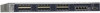
Managed Stackable Switch XSM7224S Fan Tray Removing an XSM7224S Switch Fan Tray Note: The fan tray has a hot swap capability. It is not necessary to remove the AC power when removing the fan tray. To remove the fan tray, follow these steps: 1. Loosen the two captive screws on the fan tray. 2. Remove the fan tray from the fan tray slot by pulling on the captive screws. Figure 6. Fan Tray Removal Installing an XSM7224S Switch Fan Tray To install fan tray, follow these steps: WARNING! When inserting a fan tray into the switches, do not use unnecessary force. Doing so can damage the connectors on the rear of the fan tray and on the midplane. 1. Insert the new fan tray module into the fan tray module slot, and gently push the module into the slot. 2. Align the two captive screws with the screw holes in the switch's back panel. 3. Using a screwdriver, gently tighten the captive screws. 18 | Chapter 2. Hardware Installation
-
 1
1 -
2
-
3
-
4
-
5
-
6
-
7
-
8
-
9
-
10
-
11
-
12
-
 13
13 -
 14
14 -
 15
15 -
 16
16 -
 17
17 -
 18
18 -
 19
19 -
 20
20 -
 21
21 -
 22
22 -
 23
23 -
24
-
25
-
26
-
27
-
28
-
29
-
30
 |
 |
