Panasonic WJHD316A WJHD309A User Guide - Page 11
Rear View, WJ-HD309A] - wj hd316a g
 |
View all Panasonic WJHD316A manuals
Add to My Manuals
Save this manual to your list of manuals |
Page 11 highlights
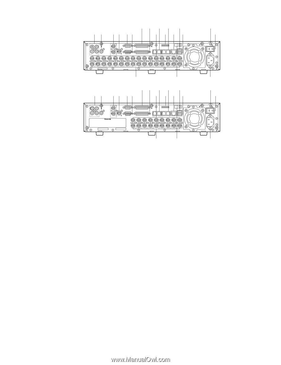
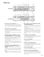
I Rear View o !0 !1 !3 !5 q w t y ui e !2 !4 !6 !8 !7 [WJ-HD316A] 3 1 1 SERIAL ALARM 4 2 AUDIO IN AUDIO OUT CASCADE OUT 2 MONITOR OUT CASCADE IN MONITOR (VGA) ALARM/CONTROL 16 15 14 13 12 11 10 9 8 7 IN OUT 16 15 14 13 12 11 10 9 8 7 VIDEO 1 8 MODE 2 1 COPY 1 DATA 6 5 RS485(CAMERA) 10/100BASE-T EXT STORAGE 4 3 2 1 6 5 4 3 2 1 qw r @0 o !0 !1 !3 !5 t y ui e !2 !4 !6 SIGNAL GND POWER AC IN !9 !8 !7 [WJ-HD309A] 3 1 4 2 AUDIO IN AUDIO OUT 1 SERIAL CASCADE OUT 2 MONITOR OUT CASCADE IN MONITOR (VGA) IN ALARM ALARM/CONTROL 9 8 7 OUT PS·Data 9 8 7 1 8 MODE 2 1 COPY 1 DATA 6 5 RS485(CAMERA) 10/100BASE-T EXT STORAGE 4 3 2 1 6 5 4 3 2 1 VIDEO SIGNAL GND POWER AC IN q Audio Input Connectors (AUDIO IN 1 - 4) These connectors, for RCA pin jacks, accept an unbalanced -10 dBV, 10 kΩ line input audio signal supplied from an external device such as a microphone amplifier. w Audio Output Connector (AUDIO OUT) This connector, for an RCA standard jack, supplies an unbalanced -10 dBV, 600 Ω line output audio signal to an external device. Recorded audio will be supplied from this connector during playback. e Video Input Connectors (CAMERA IN 1 - 16 for the WJ-HD316A/CAMERA IN 1 - 9 for the WJ-HD309A) Connect system cameras or combination cameras to these BNC connectors. Refer to page 72 for the important notice about the BNC cables to be used. A 75 Ω termination is made unless the video output terminal is connected. To connect combination cameras, connect them to the CAMERA IN 1 - 8 connectors of the WJ-HD316A, or the CAMERA IN 1 - 6 of the WJ-HD309A (accept coaxial communication). r Video Output Connectors (CAMERA OUT 1 - 16 for the WJ-HD316A/CAMERA OUT 1 - 9 for the WJHD309A) These BNC connectors supply video signals looped through the video input connectors. Refer to page 72 for the important notice about the BNC cables to be used. Note: Video signals will not be supplied from the CAMERA OUT 1 - 8 connectors if the power of the unit is off. r @0 !9 t Monitor Output Connectors (MONITOR OUT1, MONITOR OUT2/CASCADE OUT) Connect monitors to these BNC connectors. Refer to page 72 for the important notice about the BNC cables to be used. The MONITOR OUT2 connector can also be used as the CASCADE OUT connector. When using two or more units of the WJ-HD316A/WJHD309A and using the MONITOR OUT2 connector as the CASCADE OUT connector, connect with the CASCADE IN connector of another WJ-HD316A/WJHD309A. y Cascade In Connector (CASCADE IN) Connect with the CASCADE OUT connector of another WJ-HD316A/WJ-HD309A when using two or more units of the WJ-HD316A/WJ-HD309A. u Serial Connector (SERIAL) Connect a PC with this D-Sub 9-pin connector when controlling this unit. i Monitor Connector (MONITOR (VGA)) Connect a VGA monitor with this connector. The same video signal supplied to the MONITOR OUT2 connector will be supplied to this connector. o Alarm Connector (ALARM) Connect an external device such as a sensor or a door switch with this D-Sub 25-pin connector. !0 Alarm/Control Connector (ALARM/CONTROL) Connect a control switch with this D-Sub 25-pin connector when controlling this unit using an external device, or when controlling an alarm device such as a buzzer or a lamp. 11
-
 1
1 -
2
-
3
-
4
-
5
-
 6
6 -
 7
7 -
 8
8 -
 9
9 -
 10
10 -
 11
11 -
 12
12 -
 13
13 -
 14
14 -
 15
15 -
 16
16 -
17
-
18
-
19
-
20
-
21
-
22
-
23
-
24
-
25
-
26
-
27
-
28
-
29
-
30
-
31
-
32
-
33
-
34
-
35
-
36
-
37
-
38
-
39
-
40
-
41
-
42
-
43
-
44
-
45
-
46
-
47
-
48
-
49
-
50
-
51
-
52
-
53
-
54
-
55
-
56
-
57
-
58
-
59
-
60
-
61
-
62
-
63
-
64
-
65
-
66
-
67
-
68
-
69
-
70
-
71
-
72
-
73
-
74
-
75
-
76
-
77
-
78
-
79
-
80
-
81
-
82
-
83
-
84
-
85
-
86
-
87
-
88
-
89
-
90
-
91
-
92
-
93
-
94
-
95
-
96
-
97
-
98
-
99
-
100
-
101
-
102
-
103
-
104
-
105
-
106
-
107
-
108
-
109
-
110
-
111
-
112
-
113
-
114
-
115
-
116
-
117
-
118
-
119
-
120
-
121
-
122
-
123
-
124
-
125
-
126
-
127
-
128
-
129
-
130
-
131
-
132
-
133
-
134
-
135
-
136
-
137
-
138
-
139
-
140
-
141
-
142
-
143
-
144
-
145
-
146
-
147
-
148
-
149
-
150
-
151
-
152
-
153
-
154
-
155
-
156
-
157
-
158
-
159
-
160
-
161
-
162
-
163
-
164
-
165
-
166
-
167
-
168
-
169
-
170
-
171
-
172
-
173
-
174
-
175
-
176
-
177
-
178
-
179
-
180
-
181
-
182
 |
 |