Panasonic WJHD316A WJHD309A User Guide - Page 64
OPERATION OF THE UNIT IN THE CASCADE CONNECTION, Setup, Operation using the buttons on the front panel - wj hd316a digital disk recorder
 |
View all Panasonic WJHD316A manuals
Add to My Manuals
Save this manual to your list of manuals |
Page 64 highlights
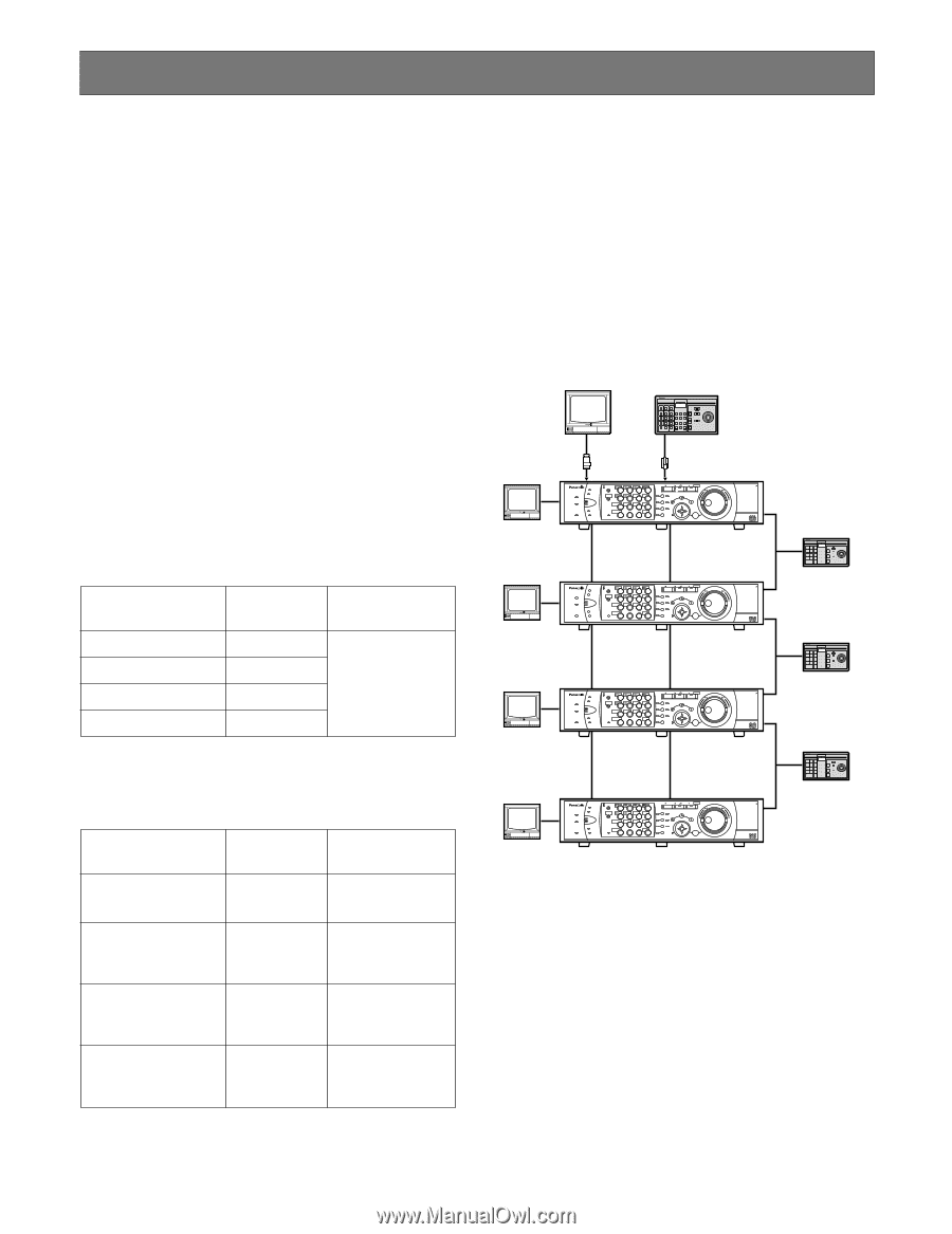
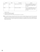
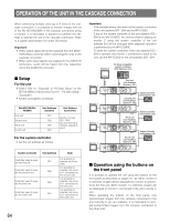
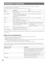
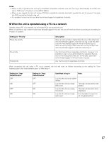
OPERATION OF THE UNIT IN THE CASCADE CONNECTION When connecting multiple units (up to 4 units) in the cascade connection, it is possible to monitor images from all of the WJ-HD316A/309A in the cascade connection using a monitor. It is necessary in advance to perform the settings to operate the unit in the cascade connection. Refer to a system administrator for further information. Important: • Video output signal will not be supplied from the MONITOR (VGA) connector when connecting the units in the cascade connection. • When audio input signals are supplied to the AUDIO IN connectors, audio will be heard from the respective unit to the AUDIO IN connector. I Setup For the unit • Select "ON" for "Cascade" of "PS.Data Setup" on the SETUP MENU (Advanced) ("Comm" - PS.data Setup" "Cascade"). • Set the unit address as follows. WJ-HD316A/WJHD309A First unit Second unit Third unit Fourth unit Unit Address (System) Unit Address (Controller) 001 Number except 002 001 - 004 (Do not allocate a 003 number already in use.) 004 For the system controller • Set the unit address as follows. System controller Unit Address Note Controller used to operate the first unit Controller used to operate the second unit Controller used to operate the third unit Controller used to operate the fourth unit It is possible to 001 operate all of four units. It is possible to 002 operate only monitor 1 connected to the second unit. It is possible to 003 operate only monitor 1 connected to the third unit. It is possible to 004 operate only monitor 1 connected to the fourth unit. 64 Important: This example works only when all the system controllers of the unit address 002 - 004 are the WV-CU650. If any of the system controller of the unit address 002 004 is the WV-CU360C, the camera channel playing on monitor 2 using the system controller of the unit address 001 will be changed when playback operation is performed by the WV-CU360C. To allow the system controllers of the unit address 002 004 to operate only monitor 1 connected to each of the unit, use the WV-CU650 for the unit address 002 - 004. Monitor 2 PS·Data compatible system controller (Unit Address: 001) System Controller Monitor 1 Monitor 1 Monitor 1 Monitor 1 First unit (Unit Address (System): 001) ALARM ALARM SUSPEND OPERATE TIMER ERROR ALARM RESET HDD 1 HDD 2 MONITOR1 MONITOR2 1234 STOP PLAY PAUSE REC - REC STOP REV FWD PAN/ GOTO SHIFT SEQ OSD TILT LAST SEARCH 5 6 7 8 ZOOM/ PAN/TILT A-B SLOW SETUP /ESC FOCUS REPEAT - + DISK SELECT COPY TEXT MARK 9 10/0 11 12 IRIS LISTED EL-ZOOM LOGOUT PRESET 13 14 15 16 /AUTO SET BUSY PULL Digital Disk Recorder WJ-HD A Second unit (Unit Address (System): 002) ALARM ALARM SUSPEND OPERATE TIMER ERROR ALARM RESET HDD 1 HDD 2 MONITOR1 MONITOR2 1234 STOP PLAY PAUSE REC - REC STOP REV FWD PAN/ GOTO SHIFT SEQ OSD TILT LAST SEARCH 5 6 7 8 ZOOM/ PAN/TILT A-B SLOW SETUP /ESC FOCUS REPEAT - + DISK SELECT COPY TEXT MARK 9 10/0 11 12 IRIS LISTED EL-ZOOM LOGOUT PRESET 13 14 15 16 /AUTO SET BUSY PULL Digital Disk Recorder WJ-HD A Third unit (Unit Address (System): 003) ALARM ALARM SUSPEND OPERATE TIMER ERROR ALARM RESET HDD 1 HDD 2 MONITOR1 MONITOR2 1234 STOP PLAY PAUSE REC - REC STOP REV FWD PAN/ GOTO SHIFT SEQ OSD TILT LAST SEARCH 5 6 7 8 ZOOM/ PAN/TILT A-B SLOW SETUP /ESC FOCUS REPEAT - + DISK SELECT COPY TEXT MARK 9 10/0 11 12 IRIS LISTED EL-ZOOM LOGOUT PRESET 13 14 15 16 /AUTO SET BUSY PULL Digital Disk Recorder WJ-HD A Fourth unit (Unit Address (System): 004) ALARM ALARM SUSPEND OPERATE TIMER ERROR ALARM RESET HDD 1 HDD 2 MONITOR1 MONITOR2 1234 STOP PLAY PAUSE REC - REC STOP REV FWD PAN/ GOTO SHIFT SEQ OSD TILT LAST SEARCH 5 6 7 8 ZOOM/ PAN/TILT A-B SLOW SETUP /ESC FOCUS REPEAT - + DISK SELECT COPY TEXT MARK 9 10/0 11 12 IRIS LISTED EL-ZOOM LOGOUT PRESET 13 14 15 16 /AUTO SET BUSY PULL Digital Disk Recorder WJ-HD A System Controller (Unit Address: 002) System Controller System Controller (Unit Address: 003) System Controller System Controller (Unit Address: 004) System Controller I Operation using the buttons on the front panel It is possible to operate the unit using the buttons on the front panel as described on pages 18 - 53. When monitor 2 is selected, images will be displayed on monitor 2 connected to the first unit. When monitor 1 is selected, images will be displayed on monitor 1 connected to the unit currently in use. When operating the buttons on the front panel, only live/recorded images from the cameras connected to the unit currently in use are available. It is impossible to operate live/recorded images from the cameras connected to the other units.
-
 1
1 -
2
-
3
-
4
-
5
-
6
-
7
-
8
-
9
-
10
-
11
-
12
-
13
-
14
-
15
-
16
-
17
-
18
-
19
-
20
-
21
-
22
-
23
-
24
-
25
-
26
-
27
-
28
-
29
-
30
-
31
-
32
-
33
-
34
-
35
-
36
-
37
-
38
-
39
-
40
-
41
-
42
-
43
-
44
-
45
-
46
-
47
-
48
-
49
-
50
-
51
-
52
-
53
-
54
-
55
-
56
-
57
-
58
-
 59
59 -
 60
60 -
 61
61 -
 62
62 -
 63
63 -
 64
64 -
 65
65 -
 66
66 -
 67
67 -
 68
68 -
 69
69 -
70
-
71
-
72
-
73
-
74
-
75
-
76
-
77
-
78
-
79
-
80
-
81
-
82
-
83
-
84
-
85
-
86
-
87
-
88
-
89
-
90
-
91
-
92
-
93
-
94
-
95
-
96
-
97
-
98
-
99
-
100
-
101
-
102
-
103
-
104
-
105
-
106
-
107
-
108
-
109
-
110
-
111
-
112
-
113
-
114
-
115
-
116
-
117
-
118
-
119
-
120
-
121
-
122
-
123
-
124
-
125
-
126
-
127
-
128
-
129
-
130
-
131
-
132
-
133
-
134
-
135
-
136
-
137
-
138
-
139
-
140
-
141
-
142
-
143
-
144
-
145
-
146
-
147
-
148
-
149
-
150
-
151
-
152
-
153
-
154
-
155
-
156
-
157
-
158
-
159
-
160
-
161
-
162
-
163
-
164
-
165
-
166
-
167
-
168
-
169
-
170
-
171
-
172
-
173
-
174
-
175
-
176
-
177
-
178
-
179
-
180
-
181
-
182
 |
 |