Panasonic WJHDE300 WJHDE300 User Guide - Page 15
Cable Connections, Connect the OUT port of unit #1 and the IN port of unit - cameras
 |
View all Panasonic WJHDE300 manuals
Add to My Manuals
Save this manual to your list of manuals |
Page 15 highlights
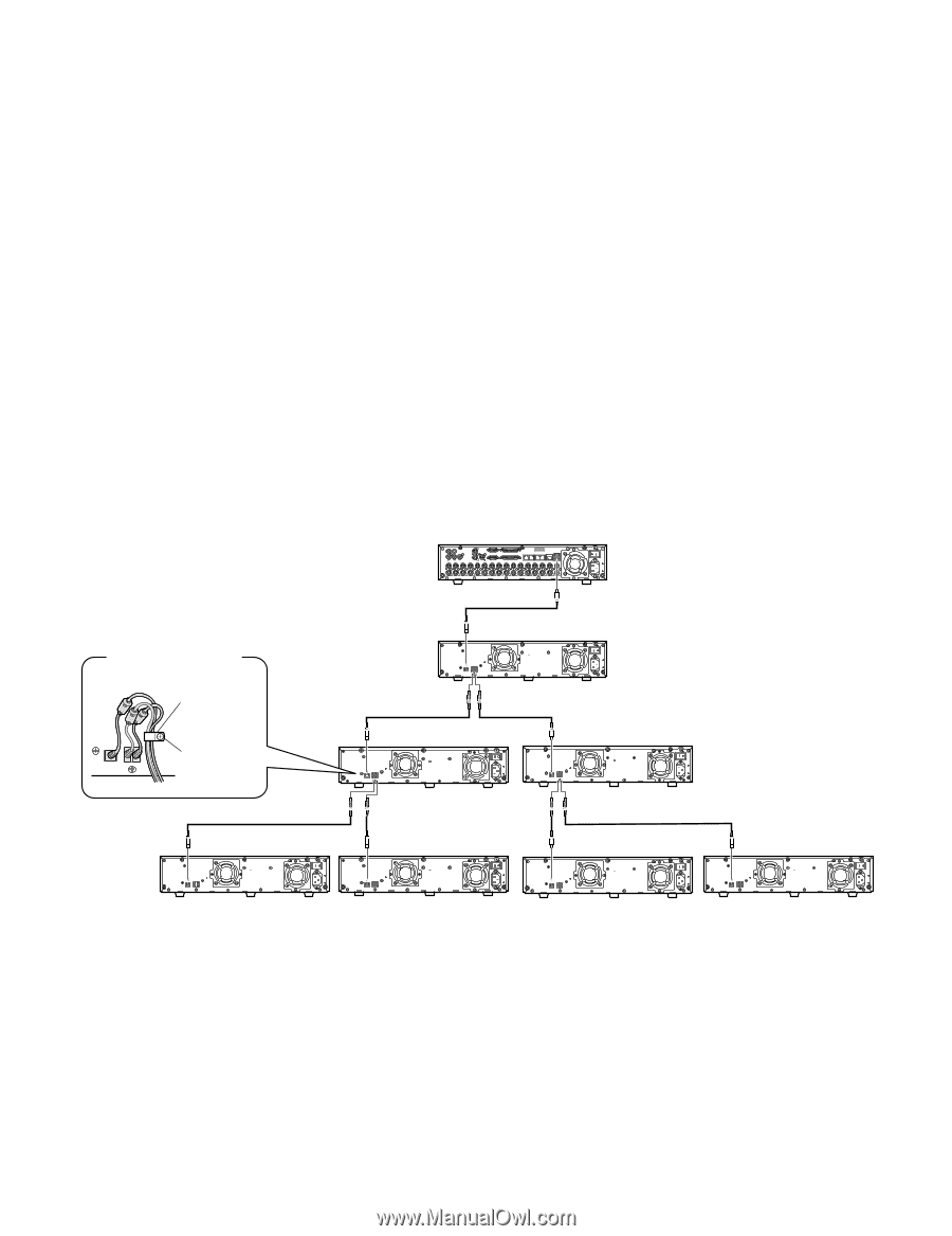
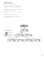
● Cable Connections The figure below shows cable connections. 1. Connect the EXT STORAGE port of the recorder and the IN port of extension unit #1 using the supplied serial cable. 2. Connect the OUT port of unit #1 and the IN port of unit #2 using the supplied serial cable. 3. Repeat connections in the same way for the remaining units. 4. Confirm the cable layout after connections. 5. Secure the cables using the clamp (supplied) and fix it to the rear of the units. WJ-HD300 Series 4 1 1 SERIAL ALARM 3 2 AUDIO IN AUDIO OUT CASCAKE OUT 2 MONITOR OUT CASCADE IN MONITOR (VGA) ALARM/CONTOROL 16 15 14 13 12 11 10 9 8 7 IN OUT 16 15 14 13 12 11 10 9 8 7 CAMERA MODE COPY PSÆDATA 6 5 RS-485(CAMERA) 10/100BASE-T EXIT STORAGE 4 3 2 1 6 5 4 3 2 1 EXT STORAGE SIGNAL GND POWER AC IN How to fix the cables EXT IN OUT 21 Cable clamp Screw for the cable clamp IN WJ-HDE300 #1 EXT IN OUT 21 SIGNAL GND POWER AC IN OUT2 OUT1 IN WJ-HDE300 #2 EXT IN OUT 21 SIGNAL GND POWER AC IN IN WJ-HDE300 #3 EXT IN OUT 21 SIGNAL GND POWER AC IN OUT2 OUT1 OUT2 OUT1 IN EXT IN OUT 21 WJ-HDE300 #4 SIGNAL GND POWER AC IN IN WJ-HDE300 #5 EXT IN OUT 21 SIGNAL GND POWER AC IN IN EXT IN OUT 21 WJ-HDE300 #6 SIGNAL GND POWER AC IN IN WJ-HDE300 #7 EXT IN OUT 21 SIGNAL GND POWER AC IN 15
-
 1
1 -
2
-
3
-
4
-
5
-
6
-
7
-
8
-
9
-
 10
10 -
 11
11 -
 12
12 -
 13
13 -
 14
14 -
 15
15 -
 16
16 -
 17
17 -
 18
18 -
 19
19 -
 20
20
 |
 |