Panasonic WJHDE300 WJHDE300 User Guide - Page 9
Replacing/Mounting HDDs
 |
View all Panasonic WJHDE300 manuals
Add to My Manuals
Save this manual to your list of manuals |
Page 9 highlights
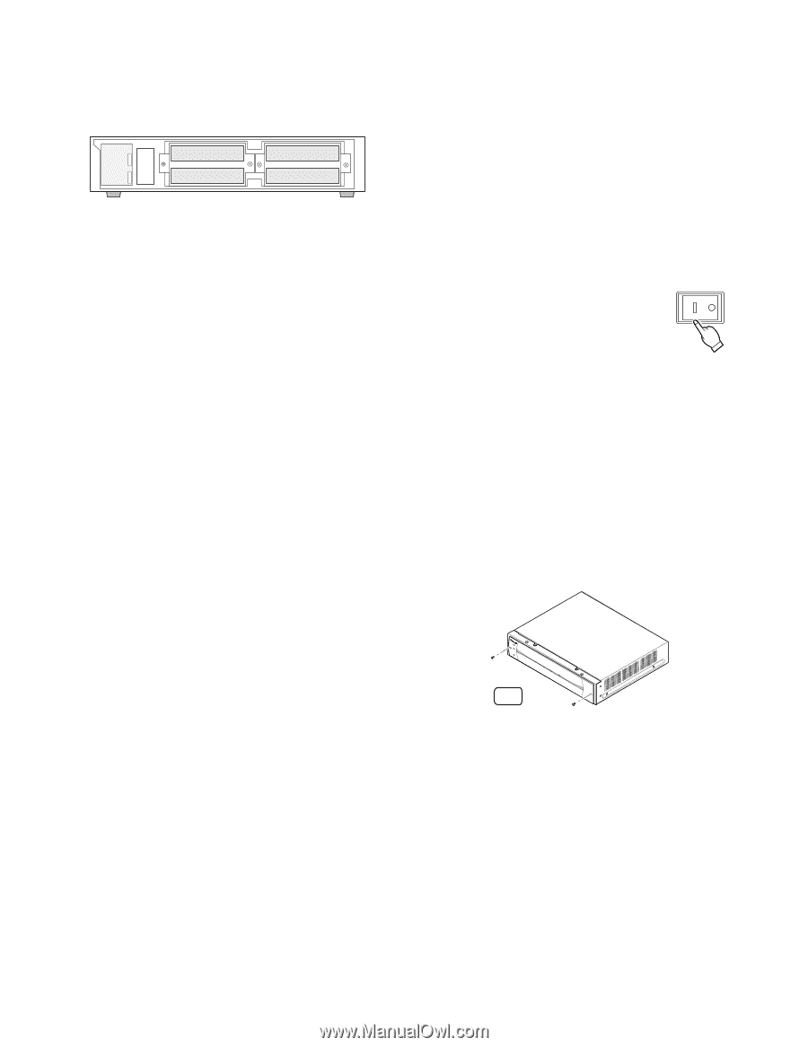
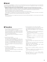
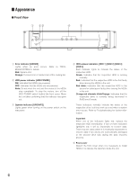
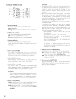
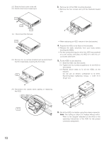
■ Replacing/Mounting HDDs Up to four HDDs (locally procured) can be installed in an extension unit. HDD 2 HDD 1 HDD 4 HDD 3 The HDDs should be installed in the proper positions in order as shown above. Do not skip or reverse the order of the HDD positions. Important • The position of the MODE switch of all units in a system must be the same. • When set to RAID5, the digital disk recorder will not access the HDD preinstalled in it, but will access only the HDDs in the extension unit. • Refer to the dealer for the compatible HDDs with this unit. • The replaced/added HDDs will be formatted. SINGLE mode: Only the replaced/added HDD will be formatted. For example, when the HDD 4 of the extension unit 2 is replaced, only the HDD4 of the extension unit 2 will be formatted. RAID 5 mode: All HDDs of the extension units will be formatted when a new HDD is added or a preinstalled HDD is removed. For example, when the HDD 4 of the extension unit 2 is added, all HDDs of the extension unit 2 will be formatted. • Data readout will not be performed when the HDD positions are changed after once the system has been operated. ● Procedures 1. HDD power-off procedures Perform either of the following procedures depending on the installation situations to stop the HDD motors. Important If turning off the POWER switch of a unit, the latter units may not work because of interrupted data transmission. Case 1: When the rear of the units is accessible, turn off the power switches of the digital disk recorder and extension units, then detach all the power plugs from the outlets. POWER Case 2: When the rear of the units is inaccessible, for example mounted in a rack, open the setup menu of the digital disk recorder and set the HDD safety mode to ON (default position). The extension units will turn to the HDD power-off mode. Refer to the Operating Instructions included with the digital disk recorder for details on it. 2. Detach the front cover and the front panel. 2-1 Remove the two screws. 2 - 1 9
-
 1
1 -
2
-
3
-
 4
4 -
 5
5 -
 6
6 -
 7
7 -
 8
8 -
 9
9 -
 10
10 -
 11
11 -
 12
12 -
 13
13 -
 14
14 -
15
-
16
-
17
-
18
-
19
-
20
 |
 |