Panasonic WJHDE300 WJHDE300 User Guide - Page 8
Inside the Front Lid, HDD power switch [HDD POWER]
 |
View all Panasonic WJHDE300 manuals
Add to My Manuals
Save this manual to your list of manuals |
Page 8 highlights
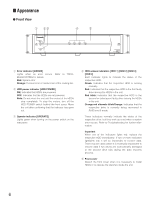
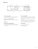
● Inside the Front Lid q' RESET !3 w' MODE !4 SINGLE RAID5 e' HDD POWER !5 OFF ON RECOVER !6 q'Error indicators Functions as same as that on the front panel. Red: System error Orange: Thermal error or malfunction of the cooling fan. w'HDD power indicator Functions as same as that on the front panel. ON: Indicates that HDDs are powered. OFF: Indicates that the HDDs are not powered. e'Operate indicator Functions as same as that on the front panel. Lights green when turning on the power switch on the rear panel. !3 Reset button [RESET] This button is located inside the unit. To access this button, it is necessary to detach the front cover. Press this button using a small screw driver (not supplied). • When SINGLE is selected After adding or replacing any of the HDDs, press this button only. Refer to page 11 and 12 for details. • When RAID 5 is selected This button is used in combination with the RECOVER button and MODE switch after adding or replacing any of the HDDs. Refer to page 11 and 12 for details. Important Do not press the RESET button and the RECOVER button simultaneously when SINGLE is selected. Otherwise, the setting of the digital disk recorder may be initialized and it may cause a malfunction. !4 Mode switch [MODE] RAID 5: Applies RAID level 5 mode (striping at the byte level also stripe error correction information). SINGLE: Applies SINGLE mode (no striping across drives for data or error correction information). Default position Important • Changing the MODE switch will not be accepted when the ERROR indicator lights red and/or when HDD 1-4 indicate a system error status by lighting red and orange. When this happens, ask your dealer to solve the error. • When set to RAID5, the HDD preinstalled in the digital disk recorder will not work. Instead, it is applied only to the HDDs installed in the extension unit and the digital disk recorder will perform storage and readout of the image data by accessing the extension unit. • The position of the MODE switch of all units in a system must be the same. • The available disk space of the unit can be logically calculated as follows. The actual space may be several percent lower than you calculated depending on the HDD type used and their combination. The most efficient way is to use the same type drives. When SINGLE is selected, it will be the sum of all the HDD sizes. When RAID 5 is selected, it will be as follows. When 3 HDDs are in the unit: It will be double the size of the smallest HDD size. When 4 HDDs are in the unit: It will be triple the size of the smallest HDD size. For example, if 4 HDDs of 80 GB, 120 GB, and two 160 GB are mounted, the available disk space will be 80 G x 3 = 240 GB. !5 HDD power switch [HDD POWER] Use this switch in the ON position for normal operation. ON: Supplies the power to the HDDs and the HDD power indicators will light. Default position OFF: Does not supply the power and the HDD power indicators will go off. !6 Recover button [RECOVER] Use this button with the RESET button after replacing HDDs used in the RAID 5 mode to start data recovery. Refer to page 12 for details. 8
-
 1
1 -
2
-
 3
3 -
 4
4 -
 5
5 -
 6
6 -
 7
7 -
 8
8 -
 9
9 -
 10
10 -
 11
11 -
 12
12 -
 13
13 -
14
-
15
-
16
-
17
-
18
-
19
-
20
 |
 |
