Pioneer DV-AX10 Owner's Manual - Page 11
Rear Panel
 |
View all Pioneer DV-AX10 manuals
Add to My Manuals
Save this manual to your list of manuals |
Page 11 highlights
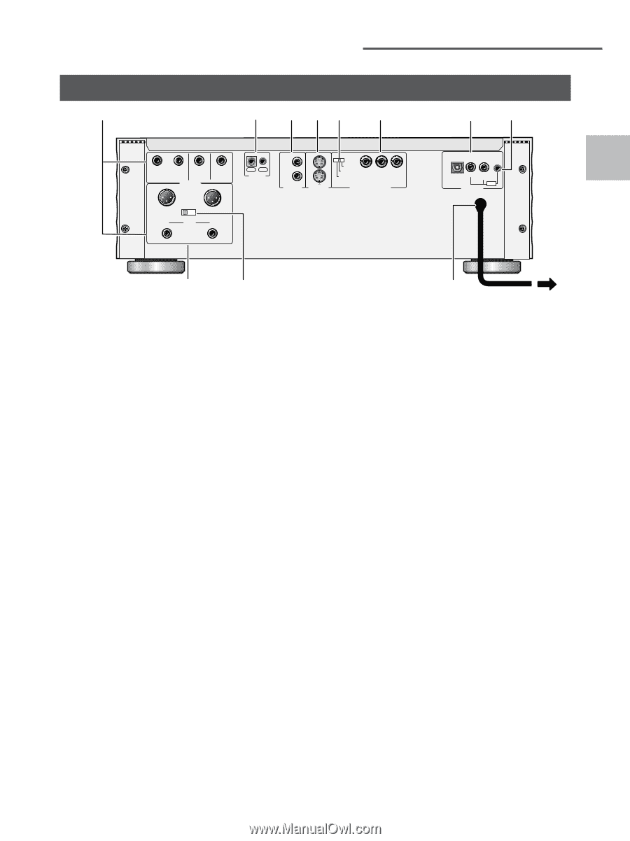
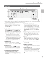
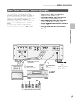
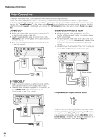
Rear Panel 1 2 3 45 6 R L SURROUND SUB WOOFER AUDIO OUT 1 - GND 2 - HOT (+) 3 - COLD (-) BALANCE OFF ON CENTER R FRONT L IN OUT CONTROL 1 1 2 VIDEO OUT 2 S-VIDEO OUT menu select 525i (480i) 525p (480p) PR PB Y COMPONENT VIDEO OUT Names and Functions 78 OPT 2COAX 1COAX PCM PDIF DIGITAL OUT NAMES AND FUNCTIONS - 0 9 * The rear and under section of this appllance are copper plated to ensure quality sound. It may sometimes happen that marks are left during the plating process, but this does not affect performance. 1 Multichannel AUDIO OUT jacks Use to output 6 discrete audio channels of decoded digital audio to a receiver or amplifier with discrete audio inputs (page 18). 2 CONTROL jacks Using a commercially available cord with a mini plug (3.5 mm dia. with no resistance) to connect this player's CONTROL IN jack to the CONTROL OUT jack of another PIONEER component bearing the Î mark, you can control the player as though it were a component in a system (system control). • If you connect for system control, you cannot operate the player directly. Point the remote control unit at the component (AV amplifier, etc.) connected to the CONTROL OUT jack to operate. • When controlling as a system, be sure to make a connection to the amplifier using an audio or video cord, even when using only digital components. • For details, refer to the operation manuals of the connected components. 3 VIDEO OUT jacks Connect to the video input on a TV, monitor, AV amplifier or receiver with video input capability (pages 14 and 16). 4 S-VIDEO OUT jacks If your TV or monitor has an S-VIDEO input, clear picture reproduction is possible by connecting the player to your TV or monitor via the S-VIDEO jack. (pages 16). 5 Component video output selection switch Use to set the scanning system (interlace, progressive, menu setting) being used by the TV, monitor, or projector connected to the COMPONENT VIDEO OUT jacks (pages 15 and 16). 6 COMPONENT VIDEO OUT jacks If your projection monitor, projector or similar component has component video inputs, you can produce a higher quality picture on your projection monitor or projector by connecting to the component video outputs on this unit. When using these jacks, be sure to set the component video output selection switch to the correct position (pages 15 and 16). 7 DIGITAL OUT jacks (coaxial(COAX)/optical (OPT)) Use to output the digital audio signal recorded on discs. You can output the digital signal via either coaxial or optical output jack to an AV amplifier or receiver (pages 15 and 17). 8 PDIF jack When using this player with the optional C-AX10 Digital Control Amplifier, connect to this jack using the PDIF cable supplied with the C-AX10 (page 17). 9 Power cord Use to connect the power cord to the wall outlet (pages 14 and 15). 0 BALANCE ON/OFF switch Use to set to ON if you are using the balanced audio outputs (page 18) - AUDIO OUT FRONT jacks Use to output two-channel audio (analog) to the audio stereo inputs on a TV or stereo amplifier. If you are connecting to a receiver that has both digital and analog input jacks for DVD player connection, it may be beneficial to make both connections (pages 15 and 18). 11 En
-
 1
1 -
2
-
3
-
4
-
5
-
 6
6 -
 7
7 -
 8
8 -
 9
9 -
 10
10 -
 11
11 -
 12
12 -
 13
13 -
 14
14 -
 15
15 -
 16
16 -
17
-
18
-
19
-
20
-
21
-
22
-
23
-
24
-
25
-
26
-
27
-
28
-
29
-
30
-
31
-
32
-
33
-
34
-
35
-
36
-
37
-
38
-
39
-
40
-
41
-
42
-
43
-
44
-
45
-
46
-
47
-
48
-
49
-
50
-
51
-
52
-
53
-
54
-
55
-
56
-
57
-
58
-
59
-
60
-
61
-
62
-
63
-
64
-
65
-
66
-
67
-
68
-
69
-
70
-
71
-
72
-
73
-
74
-
75
-
76
 |
 |