Pioneer SC-LX501 Basic Manual English/French - Page 30
Rear Panel
 |
View all Pioneer SC-LX501 manuals
Add to My Manuals
Save this manual to your list of manuals |
Page 30 highlights
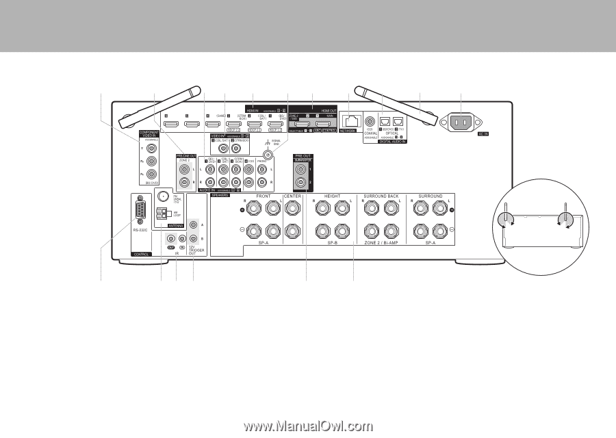
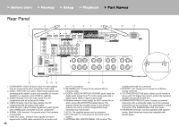
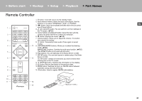
> Before start > Hookup > Setup > Playback > Part Names Rear Panel 1 2 34 5 6 7 8 9 10 11 10 12 13 14 15 1. COMPONENT VIDEO IN jacks: Input the video signals from AV components with a component video cable. 2. ZONE 2 PRE/LINE OUT jacks: Output audio signals with an analog audio cable to a pre-main amplifier or a power amplifier in a separate room (ZONE 2). (P18) 3. AUDIO IN jacks: Input the audio signal from AV components with an analog audio cable. 4. VIDEO IN jacks: Input the video signals from AV components with an analog video cable. 5. HDMI IN jacks: Transmit video signals and audio signals with a HDMI cable connected to an AV component. 6. SIGNAL GND terminal: The ground wire of the turntable is connected. 7. HDMI OUT jacks: Transmit video signals and audio signals with a HDMI cable connected to a monitor such 30 16 17 as a TV or projector. 8. NETWORK port: Connect to the network with an Ethernet cable. 9. DIGITAL AUDIO IN OPTICAL/COAXIAL jacks: Input the digital audio signals from TV or AV components with a digital optical cable or digital coaxial cable. 10.Wireless antenna: Used upright for Wi-Fi connection or when using a BLUETOOTH enabled device. The diagram shows the movable range for the wireless antenna. Do not try to force it beyond this range otherwise you may break it. 11. AC IN: The supplied power cord is connected. 12.RS-232C port: For connection to the home control system. 13.ANTENNA AM LOOP/FM UNBAL 75Ω terminal: The supplied antennas are connected. 14.IR IN/OUT port: Allows you to connect a multiroom remote control kit. 15.12V TRIGGER OUT A/B jacks: Allows you to connect a device with 12V trigger input jack to enable link operation between the device and the unit. 16.SUBWOOFER PRE OUT jacks: Connect a powered subwoofer with a subwoofer cable. Up to two powered subwoofers can be connected. The same signal is output from each of the SUBWOOFER PRE OUT jacks. 17.SPEAKERS terminals: Connect speakers with speaker cables. (North American models are compatible with banana plugs.)
-
 1
1 -
2
-
3
-
4
-
5
-
6
-
7
-
8
-
9
-
10
-
11
-
12
-
13
-
14
-
15
-
16
-
17
-
18
-
19
-
20
-
21
-
22
-
23
-
24
-
 25
25 -
 26
26 -
 27
27 -
 28
28 -
 29
29 -
 30
30 -
 31
31 -
 32
32 -
 33
33 -
 34
34 -
 35
35 -
36
-
37
-
38
-
39
-
40
-
41
-
42
-
43
-
44
-
45
-
46
-
47
-
48
-
49
-
50
-
51
-
52
-
53
-
54
-
55
-
56
-
57
-
58
-
59
-
60
-
61
-
62
-
63
-
64
-
65
-
66
-
67
-
68
 |
 |