Pyle PWD901 User Manual - Page 13
ALARM MODULE WIRING, Pin Door Lock Harness, Pin Main Harness
 |
View all Pyle PWD901 manuals
Add to My Manuals
Save this manual to your list of manuals |
Page 13 highlights
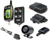
ALARM MODULE WIRING 6-Pin Door Lock Harness Plug-in connector port for door lock harness. See Door Lock Wiring Diagrams • BLUE/BLACK WIRE - Lock relay N/C (87a) • BLUE WIRE - Lock relay Common (30). • GREEN WIRE - Unlock relay Common (30). • GREEN/BLACK WIRE - Unlock relay N/C (87a). • BLACK/RED WIRES - Lock/Unlock relays N/O (87). Connect this wire to the 14-pin harness short RED wire or short BLACK wire for polarity input. See description for RED and BLACK wires below. NOTE: For vacuum locking systems, cut the BLACK/RED jumper to allow separate polarity inputs for lock and unlock relays. 14-Pin Main Harness • RED WIRE - +12V Battery input. Connect the red fused wire on the main harness to a constant +12V source. Connect the short RED wire to the door lock polarity input on the 6pin harness for positive or reverse polarity lock systems. • BLACK WIRE - Ground input (-). Connect to a solid chassis ground that is clean and free of paint or dirt. Connect the short BLACK wire to the door lock polarity input on the 6-pin harness for negative lock systems. • BLUE WIRE - Dome Light output (-) 500mA. The BLUE wire can programmed for use as a 20 or 30 second timed output after either disarming the system (Dome Light) or after arming the system (Window Roll-up). See Alarm Programmable Features Dome Light (default): Connect to a relay to activate the vehicle's dome light.The dome light relay output is usually connected to the same wire used for the door trigger input (See BLUE/RED and BLUE/BLACK wires). Window Roll-up: Connect to a relay or other device to operate window modules or other desired features. • BLACK/RED WIRE - Starter defeat/anti-grind output (-) 500mA. The BLACK/RED wire is terminated beside the small YELLOW ignition jumper in a 2-pin connector for the supplied starter defeat relay socket. Connect the relay socket for starter defeat (and anti-grind protection with optional remote start module connected). The starter defeat output is programmable for normally open or normally closed operation. See Starter Defeat Relay Diagrams and Alarm Programmable Features • ORANGE/VIOLET WIRE - Brake switch input wire. Connect this wire to the brake switch wire that provides +12V when the brake pedal is pressed. This safety input must be connected when used with the optional remote start module or the remote start feature will not operate. If the remote start module is not connected, leave this wire disconnected and set Alarm Programmable Feature #3 to either button 2, 3 or 4 setting. See Alarm Programmable Features • BLUE/RED WIRE - Positive door trigger (+). Connect to the door switch circuit wire that shows +12V when the door is open. This type of door circuit is usually found on Ford vehicles. • ORANGE/WHITE WIRE - Trunk trigger (-). Connect to an optional trunk pin switch that shows ground when the trunk is open. • GREEN/BLACK WIRE - Parking Light output (+) 7.5A relay. Connect to the vehicle's parking light wire. If the vehicle is equipped with more than four parking lights a relay is required. For vehicle's with independent left and right parking light circuits, connect the GREEN/BLACK wire to one side and the GREEN/YELLOW wire to the other. NOTE: Do not connect the GREEN/BLACK or GREEN/YELLOW wire to the vehicle's headlight circuit. 13
-
 1
1 -
2
-
3
-
4
-
5
-
6
-
7
-
 8
8 -
 9
9 -
 10
10 -
 11
11 -
 12
12 -
 13
13 -
 14
14 -
 15
15 -
 16
16 -
 17
17 -
 18
18 -
19
-
20
-
21
-
22
-
23
-
24
 |
 |
