Pyle PWD901 User Manual - Page 24
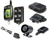
Alarm Module Wiring Diagram, Optional Start Module Wiring Diagram
 |
View all Pyle PWD901 manuals
Add to My Manuals
Save this manual to your list of manuals |
Page 24 highlights
module side view ALARM MODULE WIRING DIAGRAM 3-Pin Data-Link cable 2-Pin Shock Sensor Blue Black/Red Blue/Black Green Black/Red Green/Black Lock relay common 30 [10A fuse] Lock relay normally open 87 Lock relay normally closed 87a Unlock relay common 30 [10A fuse] Unlock relay normally open 87 Unlock relay normally closed 87a Red Black Blue Black/Yellow Orange/Violet Blue/Red Orange/White Green/Black Green/Yellow Yellow Gray Yellow/Black Blue/Black Orange/Gray +12V Battery input (+) Ground (-) Dome light output (-) 500mA Starter defeat/anti-grind output (-) 500mA Brake input (+) Door trigger input (+) Trunk input (-) Parking light output (+ built-in relay) Parking light output (+ built-in relay) Ignition input (+) Siren output (+) 3A Auxiliary output (-) 500mA Door trigger input (-) Hood input (-) Optional sensor +12V output Ground Optional sensor instant trigger input (-) Optional sensor warn input (-) Valet switch LED Antenna cable Not Used OPTIONAL START MODULE WIRING DIAGRAM © 2004 Red Green Blue Yellow Black/Yellow Black/Yellow +12V Battery input (+) Ignition 2 output (+) Accessory output (+) Ignition 1 input (+) Starter output (+) (small gauge) not used Black Gray/Black Orange/Violet Pink Black/Red Orange/Gray Yellow/Black Ground (-) Tachometer input Glow plug input (+/-) Remote start input (-) Remote start output (-) 500mA Hood input (-) Progammable output (-) 500mA Data-Link Cable (links alarm and start module) DIP Switches - Default setting is OFF position (see Remote Start Dip Switches) Starter Test Button RPM Signal LED 64-72.50, 9/04 Rev. 2 24
-
 1
1 -
2
-
3
-
4
-
5
-
6
-
7
-
8
-
9
-
10
-
11
-
12
-
13
-
14
-
15
-
16
-
17
-
18
-
 19
19 -
 20
20 -
 21
21 -
 22
22 -
 23
23 -
 24
24
 |
 |
