Rheem RAMP-JEZ Installation Instructions - Page 11
Outdoor Unit Below Indoor Coil, Tubing Installation
 |
View all Rheem RAMP-JEZ manuals
Add to My Manuals
Save this manual to your list of manuals |
Page 11 highlights
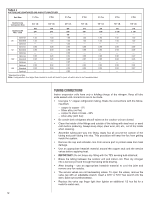
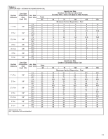
5. Capillary Tube Coil: DO NOT exceed the Table values for vertical separation for capillary tube coils. 6. Always use the smallest liquid line size permitted to minimize the system charge. 7. Taabbllee 64 mmaayy bbee used for sizing horizontal runs. OUTDOOR UNIT BELOW INDOOR COIL Keep the vertical separation to a minimum. Use the following guidelines when installing the unit: 1. DO NOT exceed the vveerrttiiccaall sseeppaarraattiioonnss aass iinnddiiccaatteeddoonnTTaabbllee 56.. 2. Always use the smallest liquid line size permitted to minimize system charge. 3. No changes are required for either flow check piston coils or expansions coils. 4. Taabbllee 65 mmaayy bbee used for sizing horizontal runs. TUBING INSTALLATION Observe the following when installing correctly sized type "L" refrigerant tubing between the condensing unit and evaporator coil: • If a portion of the liquid line passes through a hot area where liquid refrigerant can be heated to form vapor, insulating the liquid line is required. • Use clean, dehydrated, sealed refrigeration grade tubing. • Always keep tubing sealed until tubing is in place and connections are to be made. • Blow out the liquid and vapor lines with dry nitrogen before connecting to the outdoor unit and indoor coil. Any debris in the line set will end up plugging the expansion device. • As an added precaution, a high quality filter drier is standard on R-410A units. • Do not allow the vapor line and liquid line to be in contact with each other. This causes an undesirable heat transfer resulting in capacity loss and increased power consumption. The vapor line must be insulated. • If tubing has been cut, make sure ends are deburred while holding in a position to prevent chips from falling into tubing. Burrs such as those caused by tubing cutters can affect performance dramatically, particularly on small liquid line sizes. • For best operation, keep tubing run as short as possible with a minimum number of elbows or bends. • Locations where the tubing will be exposed to mechanical damage should be avoided. If it is necessary to use such locations, the copper tubing should be housed to prevent damage. • If tubing is to be run underground, it must be run in a sealed watertight chase. • Use care in routing tubing and do not kink or twist. Use a good tubing bender on the vapor line to prevent kinking. • Route the tubing using temporary hangers, then straighten the tubing and install permanent hangers. Line must be adequately supported. • The vapor line must be insulated to prevent dripping (sweating) and prevent performance losses. Armaflex and Rubatex are satisfactory insulations for this purpose. Use 1/2" minimum insulation thickness, additional insulation may be required for long runs. • Check Taabbllee53ffoorrtthheeccoorrrreeccttvvaappoorrlilnineessizizee..cChheecckkTaTbalbele6sf4oratnhde 5cofrorretchteliqcuoirdlriencet sliiqzuei.d line size. 11
-
 1
1 -
2
-
3
-
4
-
5
-
 6
6 -
 7
7 -
 8
8 -
 9
9 -
 10
10 -
 11
11 -
 12
12 -
 13
13 -
 14
14 -
 15
15 -
 16
16 -
17
-
18
-
19
-
20
-
21
-
22
-
23
-
24
-
25
-
26
-
27
-
28
 |
 |